Product Description
Dedicated Couplings Adaptors for Ductile Iron Pipes ISO 2531/EN545 EN 14525, ANSI/AWWA C219
Description
SYI can supply the Dedicated Couplings dedicated Couplings, dedicated to connect the ductile iron pipe (upto DN2200)
SYI Dedicated Couplings DIMENSIONS
|
CHINAMFG S. N. |
DN |
pipe O.D. |
O.D. Tolerance |
D2 |
H |
L |
Min. pipe end prepared length |
|
|
|
mm |
|||||||
|
DC40 |
40 |
56 |
+1.0 |
-3.0 |
120 |
102 |
166 |
100 |
|
DC50 |
50 |
66 |
+1.0 |
-3.0 |
126 |
102 |
166 |
100 |
|
DC60 |
60 |
77 |
+1.0 |
-3.0 |
135 |
102 |
166 |
100 |
|
DC65 |
65 |
82 |
+1.0 |
-3.0 |
156 |
102 |
166 |
100 |
|
DC80 |
80 |
98 |
+1.0 |
-3.0 |
184 |
102 |
166 |
100 |
|
DC100 |
100 |
118 |
+1.0 |
-3.0 |
205 |
102 |
166 |
100 |
|
DC125 |
125 |
144 |
+1.0 |
-3.0 |
232 |
102 |
166 |
100 |
|
DC150 |
150 |
170 |
+1.0 |
-3.0 |
264 |
102 |
173 |
100 |
|
DC200 |
200 |
222 |
+1.0 |
-3.5 |
315 |
102 |
173 |
100 |
|
DC250 |
250 |
274 |
+1.0 |
-3.5 |
374 |
102 |
173 |
100 |
|
DC300 |
300 |
326 |
+1.0 |
-3.5 |
426 |
102 |
173 |
100 |
|
DC350 |
350 |
378 |
+1.0 |
-3.5 |
494 |
152 |
254 |
150 |
|
DC400 |
400 |
429 |
+1.0 |
-4.0 |
544 |
152 |
254 |
150 |
|
DC450 |
450 |
480 |
+1.0 |
-4.0 |
595 |
152 |
254 |
150 |
|
DC500 |
500 |
532 |
+1.0 |
-4.0 |
650 |
152 |
254 |
150 |
|
DC600 |
600 |
635 |
+1.0 |
-4.5 |
753 |
152 |
254 |
150 |
|
DC700 |
700 |
738 |
+1.0 |
-4.5 |
858 |
152 |
254 |
150 |
|
DC800 |
800 |
842 |
+1.0 |
-4.5 |
962 |
152 |
254 |
150 |
|
DC900 |
900 |
945 |
+1.0 |
-5.0 |
1070 |
178 |
280 |
150 |
|
DC1000 |
1000 |
1048 |
+1.0 |
-5.0 |
1173 |
178 |
280 |
150 |
|
DC1100 |
1100 |
1152 |
+1.0 |
-6.0 |
1282 |
178 |
280 |
150 |
|
DC1200 |
1200 |
1255 |
+1.0 |
-6.0 |
1385 |
178 |
280 |
150 |
|
DC1400 |
1400 |
1462 |
+1.0 |
-6.0 |
1592 |
178 |
295 |
150 |
|
DC1500 |
1500 |
1565 |
+1.0 |
-6.0 |
1691 |
178 |
295 |
150 |
|
DC1600 |
1600 |
1668 |
+1.0 |
-6.0 |
1798 |
178 |
295 |
150 |
|
DC1800 |
1800 |
1875 |
+1.0 |
-6.0 |
2015 |
254 |
375 |
150/300 |
|
DC2000 |
2000 |
2082 |
+1.0 |
-6.0 |
2222 |
254 |
375 |
150/300 |
|
DC2200 |
2200 |
2288 |
+1.0 |
-6.0 |
2415 |
254 |
375 |
150/300 |
For other sizes not mentioned above, please contact us. We have right to change the data without further notice.
1. Material
BODY: Ductile Iron grade 500-7/450-10 in accordance with ISO 1083 or 70-50-05/65-45-12 with ASTM A536
GLAND: Ductile Iron grade 500-7/450-10 in accordance with ISO 1083 or 70-50-05/65-45-12 with ASTM A536
GASKET: Rubber E.P.D.M./SBR/NBR in accordance with EN 681.1
D-BOLTS AND NUTS: Carbon Steel Grade 8.8 with dacromet coating
2. Working Pressure: 16 Bar or 250 PSI
3. Fluid Temperature: 0°C – 50°C, excluding frost
4. Allowed Angular Deflection: 6°
5. Joint Gap:19mm
6. Coating
|
External Coatings: |
Internal Coatings: |
7.Reference Rules
Designed and tested in accordance with EN14525, ANSI/AWWA C219 and EN545
Package
Packing: Different package CHINAMFG your request,like wood cases&pallets,ply-wood crates&pallets,steel crates&pallets and etc.
Quality Control
Company Profile
CHINAMFG has continually invested in better technology and production facilities. More than 4,000 patterns
are ready. We are capable to finish all the production processes from moulding, shot-blasting, machining, coating to packaging. We have over 100,000 m2 foundry land including:
-10,000 m2 of the pattern, sand mixing, polishing, machining, hydraulic pressure, coating, packaging workshops;
-4,000 m2 of 3 green sand moulding workshops and 1 resin sand moulding workshops;
-3,000 m2 of automatic moulding machine line and epoxy coating line
-professional laboratory
-machining shop
-and our own tooling shop
Strict process and operating regulations together with perfect quality assurance system making every production step under control. All the products are subject to tests and inspections including composition analysis, metallographic examination, dimension & surface finish inspection, ring test, tensile test, hardness test, hydrostatic test, CHINAMFG and coating test to be sure that the products meet the requirements of the standards.
Since 2009, CHINAMFG Pipeline has developed from a pipes & fittings seller to a professional project solution provider, including the 1 stop service and solution from pipes, fittings, couplings & flanged adaptors, valves, fire hydrants, to water CHINAMFG and accessories.
SYI products have served 111 countries CHINAMFG up to now!
Most of these customers cooperated with CHINAMFG for more than 20 years!
We value long term cooperation relationship mostly!
Welcome to send us an inquiry for more details and price!!!
P
/* January 22, 2571 19:08:37 */!function(){function s(e,r){var a,o={};try{e&&e.split(“,”).forEach(function(e,t){e&&(a=e.match(/(.*?):(.*)$/))&&1
| After-sales Service: | Online Solution |
|---|---|
| Warranty: | 1 Year |
| Connection: | Press Connection |
| Structure: | Universal |
| Flexible or Rigid: | Flexible |
| Material: | Iron |
| Samples: |
US$ 50/Piece
1 Piece(Min.Order) | |
|---|
| Customization: |
Available
| Customized Request |
|---|

How do you calculate the torque capacity of a universal joint?
Calculating the torque capacity of a universal joint involves considering various factors such as the joint’s design, material properties, and operating conditions. Here’s a detailed explanation:
The torque capacity of a universal joint is determined by several key parameters:
- Maximum Allowable Angle: The maximum allowable angle, often referred to as the “operating angle,” is the maximum angle at which the universal joint can operate without compromising its performance and integrity. It is typically specified by the manufacturer and depends on the joint’s design and construction.
- Design Factor: The design factor accounts for safety margins and variations in load conditions. It is a dimensionless factor typically ranging from 1.5 to 2.0, and it is multiplied by the calculated torque to ensure the joint can handle occasional peak loads or unexpected variations.
- Material Properties: The material properties of the universal joint’s components, such as the yokes, cross, and bearings, play a crucial role in determining its torque capacity. Factors such as the yield strength, ultimate tensile strength, and fatigue strength of the materials are considered in the calculations.
- Equivalent Torque: The equivalent torque is the torque value that represents the combined effect of the applied torque and the misalignment angle. It is calculated by multiplying the applied torque by a factor that accounts for the misalignment angle and the joint’s design characteristics. This factor is often provided in manufacturer specifications or can be determined through empirical testing.
- Torque Calculation: To calculate the torque capacity of a universal joint, the following formula can be used:
Torque Capacity = (Equivalent Torque × Design Factor) / Safety Factor
The safety factor is an additional multiplier applied to ensure a conservative and reliable design. The value of the safety factor depends on the specific application and industry standards but is typically in the range of 1.5 to 2.0.
It is important to note that calculating the torque capacity of a universal joint involves complex engineering considerations, and it is recommended to consult manufacturer specifications, guidelines, or engineering experts with experience in universal joint design for accurate and reliable calculations.
In summary, the torque capacity of a universal joint is calculated by considering the maximum allowable angle, applying a design factor, accounting for material properties, determining the equivalent torque, and applying a safety factor. Proper torque capacity calculations ensure that the universal joint can reliably handle the expected loads and misalignments in its intended application.

Can universal joints be used in agricultural equipment?
Yes, universal joints can be used in agricultural equipment. Here’s a detailed explanation:
Universal joints are commonly employed in various types of agricultural equipment and machinery. They offer several advantages that make them suitable for agricultural applications. Here are some key points to consider:
- Torque Transmission: Agricultural equipment often requires the transmission of high torque levels to perform tasks such as plowing, tilling, harvesting, or powering other implements. Universal joints are capable of transmitting significant amounts of torque, making them suitable for handling the power requirements of agricultural machinery.
- Flexibility: Agricultural equipment frequently operates in uneven terrain or encounters obstacles that can cause angular misalignment between the driving and driven components. Universal joints can accommodate such misalignment and transmit torque even when the shafts are not perfectly aligned. This flexibility allows agricultural machinery to navigate uneven surfaces and maintain power transfer.
- Durability: Universal joints can be constructed from materials that provide high strength and durability, such as alloy steels. Agricultural equipment often operates in demanding conditions, including exposure to dust, moisture, and vibrations. Robust universal joints can withstand these harsh environments and repetitive motions, ensuring reliable performance and longevity.
- Cost-Effectiveness: Universal joints offer a cost-effective solution for torque transmission in agricultural equipment. Compared to alternative power transmission methods, such as complex gear systems or hydraulic drives, universal joints can provide a more economical option while still delivering adequate performance and reliability.
- Wide Application Range: Universal joints can be used in various agricultural equipment, including tractors, combine harvesters, balers, seeders, sprayers, and more. They are versatile components that can be integrated into different systems and configurations, allowing for efficient power transmission in a wide range of agricultural applications.
It’s important to note that the specific design and selection of universal joints for agricultural equipment should consider factors such as the torque requirements, operating conditions, maintenance practices, and safety considerations. Proper sizing, lubrication, and regular inspections are crucial for ensuring optimal performance and preventing premature wear or failure.
In summary, universal joints can indeed be used in agricultural equipment. Their torque transmission capabilities, flexibility, durability, cost-effectiveness, and versatility make them a suitable choice for power transmission in various agricultural machinery and equipment.

What is a universal joint and how does it work?
A universal joint, also known as a U-joint, is a mechanical coupling that allows for the transmission of rotary motion between two shafts that are not in line with each other. It is commonly used in applications where shafts need to transmit motion at angles or around obstacles. The universal joint consists of a cross-shaped or H-shaped yoke with bearings at the ends of each arm. Let’s explore how it works:
A universal joint typically comprises four main components:
- Input Shaft: The input shaft is the shaft that provides the initial rotary motion.
- Output Shaft: The output shaft is the shaft that receives the rotary motion from the input shaft.
- Yoke: The yoke is a cross-shaped or H-shaped component that connects the input and output shafts. It consists of two arms perpendicular to each other.
- Bearings: Bearings are located at the ends of each arm of the yoke. These bearings allow for smooth rotation and reduce friction between the yoke and the shafts.
When the input shaft rotates, it causes the yoke to rotate along with it. Due to the perpendicular arrangement of the arms, the output shaft connected to the other arm of the yoke experiences rotary motion at an angle to the input shaft.
The universal joint works by accommodating the misalignment between the input and output shafts. As the input shaft rotates, the yoke allows the output shaft to rotate freely and continuously despite any angular displacement or misalignment between the two shafts. This flexibility of the universal joint enables torque to be transmitted smoothly between the shafts while compensating for their misalignment.
During operation, the bearings at the ends of the yoke arms allow for the rotation of the yoke and the connected shafts. The bearings are often enclosed within a housing or cross-shaped cap to provide protection and retain lubrication. The design of the bearings allows for a range of motion and flexibility, allowing the yoke to move and adjust as the shafts rotate at different angles.
The universal joint is commonly used in various applications, including automotive drivelines, industrial machinery, and power transmission systems. It allows for the transmission of rotary motion at different angles and helps compensate for misalignment, eliminating the need for perfectly aligned shafts.
It is important to note that universal joints have certain limitations. They introduce a small amount of backlash or play, which can affect precision and accuracy in some applications. Furthermore, at extreme angles, the operating angles of the universal joint may become limited, potentially causing increased wear and reducing its lifespan.
Overall, the universal joint is a versatile mechanical coupling that enables the transmission of rotary motion between misaligned shafts. Its ability to accommodate angular displacement and misalignment makes it a valuable component in numerous mechanical systems.


editor by CX 2024-05-09
China manufacturer Ws Type Universal Joints Coupling with High Precision
Product Description
WS Type Universal Joint Shaft
Features:
1. It is suitable for transmission coupling space on the same plane of 2 axis angle beta β≤45°, the nominal torque transmission 11.2-1120N.
2.The WSD type is a single cross universal coupling, and the WS type is a double cross universal coupling.
3.Each section between the largest axis angle 45º.
4.The finished hole H7, according to the requirements of keyseating, 6 square hole and square hole.
5.The angle between the 2 axes is allowed in a limited range as the work requirements change.
|
NO |
Tn/N·m |
d(H7) |
D |
L0 |
L |
L1 |
m/kg |
I/kg·m2 |
||||||||||
|
WSD |
WS |
WSD |
WS |
WSD |
WS |
|||||||||||||
|
Y |
J1 |
Y |
J1 |
Y |
J1 |
Y |
J1 |
Y |
J1 |
Y |
J1 |
Y |
J1 |
|||||
|
WS1 WSD1 |
11.2 |
8 |
16 |
60 |
– |
80 |
– |
20 |
– |
20 |
0.23 |
– |
0.32 |
– |
0.06 |
– |
0.08 |
– |
|
9 |
||||||||||||||||||
|
10 |
66 |
60 |
86 |
80 |
25 |
22 |
0.2 |
0.29 |
0.05 |
0.07 |
||||||||
|
WS2 WSD2 |
22.4 |
10 |
20 |
70 |
64 |
96 |
90 |
26 |
0.64 |
0.57 |
0.93 |
0.88 |
0.1 |
0.09 |
0.15 |
0.15 |
||
|
11 |
||||||||||||||||||
|
12 |
84 |
74 |
110 |
100 |
32 |
27 |
||||||||||||
|
WS3 WSD3 |
45 |
12 |
25 |
90 |
80 |
122 |
112 |
32 |
1.45 |
1.3 |
2.1 |
1.95 |
0.17 |
0.15 |
0.24 |
0.22 |
||
|
14 |
||||||||||||||||||
|
WS4 WSD4 |
71 |
16 |
32 |
116 |
82 |
154 |
130 |
42 |
30 |
38 |
5.92 |
4.86 |
8.56 |
0.48 |
0.39 |
0.32 |
0.56 |
0.49 |
|
18 |
||||||||||||||||||
|
WS5 WSD5 |
140 |
19 |
40 |
144 |
116 |
192 |
164 |
48 |
16.3 |
12.9 |
24 |
20.6 |
0.72 |
0.59 |
1.04 |
0.91 |
||
|
20 |
52 |
38 |
||||||||||||||||
|
22 |
||||||||||||||||||
|
WS6 WSD6 |
280 |
24 |
50 |
152 |
124 |
210 |
182 |
52 |
38 |
58 |
45.7 |
36.7 |
68.9 |
59.7 |
1.28 |
1.03 |
1.89 |
1.64 |
|
25 |
172 |
136 |
330 |
194 |
62 |
44 |
||||||||||||
|
28 |
||||||||||||||||||
|
WS7 WSD7 |
560 |
30 |
60 |
226 |
182 |
296 |
252 |
82 |
60 |
70 |
148 |
117 |
207 |
177 |
2.82 |
2.31 |
3.9 |
3.38 |
|
32 |
||||||||||||||||||
|
35 |
||||||||||||||||||
|
WS8 WSD8 |
1120 |
38 |
75 |
240 |
196 |
332 |
288 |
92 |
396 |
338 |
585 |
525 |
5.03 |
4.41 |
7.25 |
6.63 |
||
|
40 |
300 |
244 |
392 |
336 |
112 |
84 |
||||||||||||
|
42 |
||||||||||||||||||
Detailed Photos
Company Profile
HangZhou CHINAMFG Machinery Manufacturing Co., Ltd. is a high-tech enterprise specializing in the design and manufacture of various types of coupling. There are 86 employees in our company, including 2 senior engineers and no fewer than 20 mechanical design and manufacture, heat treatment, welding, and other professionals.
Advanced and reasonable process, complete detection means. Our company actively introduces foreign advanced technology and equipment, on the basis of the condition, we make full use of the advantage and do more research and innovation. Strict to high quality and operate strictly in accordance with the ISO9000 quality certification system standard mode.
Our company supplies different kinds of products. High quality and reasonable price. We stick to the principle of “quality first, service first, continuous improvement and innovation to meet the customers” for the management and “zero defect, zero complaints” as the quality objective.
Our Services
1. Design Services
Our design team has experience in Cardan shafts relating to product design and development. If you have any needs for your new product or wish to make further improvements, we are here to offer our support.
2. Product Services
raw materials → Cutting → Forging →Rough machining →Shot blasting →Heat treatment →Testing →Fashioning →Cleaning→ Assembly→Packing→Shipping
3. Samples Procedure
We could develop the sample according to your requirement and amend the sample constantly to meet your need.
4. Research & Development
We usually research the new needs of the market and develop new models when there are new cars in the market.
5. Quality Control
Every step should be a particular test by Professional Staff according to the standard of ISO9001 and TS16949.
FAQ
Q 1: Are you a trading company or a manufacturer?
A: We are a professional manufacturer specializing in manufacturing
various series of couplings.
Q 2:Can you do OEM?
Yes, we can. We can do OEM & ODM for all customers with customized PDF or AI format artwork.
Q 3:How long is your delivery time?
Generally, it is 20-30 days if the goods are not in stock. It is according to quantity.
Q 4: Do you provide samples? Is it free or extra?
Yes, we could offer the sample but not for free. Actually, we have an excellent price principle, when you make the bulk order the cost of the sample will be deducted.
Q 5: How long is your warranty?
A: Our Warranty is 12 months under normal circumstances.
Q 6: What is the MOQ?
A: Usually our MOQ is 1pcs.
Q 7: Do you have inspection procedures for coupling?
A:100% self-inspection before packing.
Q 8: Can I have a visit to your factory before the order?
A: Sure, welcome to visit our factory.
Q 9: What’s your payment?
A:1) T/T.
♦Contact Us
Web: huadingcoupling
Add: No.11 HangZhou Road,Chengnan park,HangZhou City,ZheJiang Province,China
/* January 22, 2571 19:08:37 */!function(){function s(e,r){var a,o={};try{e&&e.split(“,”).forEach(function(e,t){e&&(a=e.match(/(.*?):(.*)$/))&&1
| Standard Or Nonstandard: | Standard |
|---|---|
| Shaft Hole: | 19-32 |
| Torque: | >80N.M |
| Bore Diameter: | 14mm |
| Speed: | 9000r/M |
| Structure: | Flexible |
| Customization: |
Available
| Customized Request |
|---|

Can universal joints be used in precision manufacturing equipment?
Yes, universal joints can be used in precision manufacturing equipment, depending on the specific requirements and applications. Here’s a detailed explanation:
Precision manufacturing equipment often requires precise and reliable motion transmission between different components or subsystems. Universal joints can be employed in such equipment to facilitate the transmission of rotational motion and torque while accommodating misalignment or angular variations. However, their usage in precision manufacturing equipment is subject to certain considerations:
- Motion Transmission: Universal joints are effective in transmitting rotational motion and torque across misaligned or non-collinear shafts. In precision manufacturing equipment, where precise and synchronized motion is crucial, universal joints can provide flexibility and compensate for slight misalignments or angular variations, ensuring reliable motion transfer.
- Angular Accuracy: Precision manufacturing often requires maintaining precise angular accuracy during operation. While universal joints can accommodate misalignments, they introduce certain angular errors due to their design. These errors may be acceptable or manageable depending on the specific application. However, in cases where extremely tight angular accuracy is required, alternative motion transmission mechanisms, such as precision couplings or direct drives, might be preferred.
- Backlash and Play: Universal joints can exhibit a certain degree of backlash or play, which may affect the precision of the manufacturing process. Backlash refers to the slight movement or play that occurs when reversing the direction of rotation. In precision manufacturing equipment, minimizing backlash is often critical. Careful selection of high-quality universal joints or incorporating additional mechanisms to reduce backlash, such as preloading or anti-backlash devices, might be necessary to achieve the desired precision.
- Load and Speed Considerations: When using universal joints in precision manufacturing equipment, it is essential to consider the expected loads and operating speeds. Universal joints have specific load and speed limitations, and exceeding these limits can lead to premature wear, reduced precision, or even failure. Careful selection of universal joints with appropriate load and speed ratings based on the application’s requirements is necessary to ensure optimal performance.
- Maintenance and Lubrication: Regular maintenance and proper lubrication are crucial for the reliable and precise operation of universal joints in precision manufacturing equipment. Following manufacturer guidelines regarding lubrication intervals, lubricant types, and maintenance procedures is essential. Regular inspection of the joints for wear, damage, or misalignment is also necessary to identify any issues that could affect precision.
- Application-Specific Considerations: Each precision manufacturing application may have unique requirements and constraints. Factors such as available space, environmental conditions, required precision levels, and integration with other components should be taken into account when determining the feasibility and suitability of using universal joints. Consulting with experts or manufacturers specializing in precision manufacturing equipment can help in evaluating the best motion transmission solution for a specific application.
In summary, universal joints can be used in precision manufacturing equipment to facilitate motion transmission while accommodating misalignment. However, their usage should be carefully evaluated considering factors such as angular accuracy requirements, backlash and play limitations, load and speed considerations, maintenance needs, and application-specific constraints.
What materials are commonly used in the construction of universal joints?
Universal joints are constructed using various materials that provide strength, durability, and resistance to wear and fatigue. Here’s a detailed explanation:
The choice of materials for universal joints depends on factors such as the application, load requirements, operating conditions, and cost considerations. Here are some commonly used materials:
- Steel: Steel is one of the most common materials used in universal joint construction. Alloy steels, such as 4140 or 4340, are often employed due to their high strength, toughness, and resistance to wear and fatigue. Steel universal joints can withstand heavy loads and harsh operating conditions, making them suitable for various industrial applications.
- Stainless Steel: Stainless steel is chosen for universal joints when corrosion resistance is a critical requirement. Stainless steel alloys, such as 304 or 316, offer excellent resistance to rust, oxidation, and chemical corrosion. These joints are commonly used in applications where exposure to moisture, chemicals, or harsh environments is expected.
- Cast Iron: Cast iron is occasionally used in universal joints, particularly in older or specialized applications. Cast iron provides good strength and wear resistance, but it is generally heavier and less flexible than steel. It may be used in specific situations where its properties are advantageous, such as in large industrial machinery.
- Aluminum: Aluminum universal joints are utilized when weight reduction is a priority. Aluminum alloys offer a good balance of strength and lightweight properties. These joints are commonly found in applications where weight savings are crucial, such as aerospace, automotive, or robotics.
- Bronze: Bronze is sometimes used for bearings or bushings within universal joints. Bronze alloys provide good wear resistance, low friction, and the ability to withstand high temperatures. They are often employed in applications where self-lubricating properties and resistance to galling are required. Bronze bearings can be found in universal joints used in heavy machinery, marine equipment, or agricultural machinery.
It’s worth noting that the specific choice of materials may vary depending on the manufacturer, application requirements, and industry standards. Different combinations of materials may also be used for different components within a universal joint, such as the yokes, crosses, bearings, or seals, to optimize performance and durability.
In summary, universal joints are commonly constructed using materials such as steel, stainless steel, cast iron, aluminum, and bronze. The selection of materials depends on factors like strength, durability, wear resistance, corrosion resistance, weight considerations, and specific application requirements.

Are there different types of universal joints available?
Yes, there are different types of universal joints available to suit various applications and requirements. Let’s explore some of the commonly used types:
- Single Joint (Cardan Joint): The single joint, also known as a Cardan joint, is the most basic and widely used type of universal joint. It consists of two yokes connected by a cross-shaped center piece. The yokes are typically 90 degrees out of phase with each other, allowing for angular displacement and misalignment between shafts. Single joints are commonly used in automotive drivelines and industrial applications.
- Double Joint: A double joint, also referred to as a double Cardan joint or a constant velocity joint, is an advanced version of the single joint. It consists of two single joints connected in series with an intermediate shaft in between. The use of two joints in series helps to cancel out the velocity fluctuations and reduce vibration caused by the single joint. Double joints are commonly used in automotive applications, especially in front-wheel-drive vehicles, to provide constant velocity power transmission.
- Tracta Joint: The Tracta joint, also known as a tripod joint or a three-roller joint, is a specialized type of universal joint. It consists of three rollers or balls mounted on a spider-shaped center piece. The rollers are housed in a three-lobed cup, allowing for flexibility and articulation. Tracta joints are commonly used in automotive applications, particularly in front-wheel-drive systems, to accommodate high-speed rotation and transmit torque smoothly.
- Rzeppa Joint: The Rzeppa joint is another type of constant velocity joint commonly used in automotive applications. It features six balls positioned in grooves on a central sphere. The balls are held in place by an outer housing with an inner race. Rzeppa joints provide smooth power transmission and reduced vibration, making them suitable for applications where constant velocity is required, such as drive axles in vehicles.
- Thompson Coupling: The Thompson coupling, also known as a tripodal joint, is a specialized type of universal joint. It consists of three interconnected rods with spherical ends. The arrangement allows for flexibility and misalignment compensation. Thompson couplings are often used in applications where high torque transmission is required, such as industrial machinery and power transmission systems.
These are just a few examples of the different types of universal joints available. Each type has its own advantages and is suitable for specific applications based on factors such as torque requirements, speed, angular displacement, and vibration reduction. The selection of the appropriate type of universal joint depends on the specific needs of the application.
editor by CX 2024-04-16
China best Ductile Iron Wide Range Universal Flexible Connection Dresser Pipe Coupling Joint
Product Description
Dedicated Couplings Adaptors for Ductile Iron Pipes ISO 2531/EN545 EN 14525, ANSI/AWWA C219
Description
SYI can supply the Dedicated Couplings dedicated Couplings, dedicated to connect the ductile iron pipe (upto DN2200)
SYI Dedicated Couplings DIMENSIONS
|
CHINAMFG S. N. |
DN |
pipe O.D. |
O.D. Tolerance |
D2 |
H |
L |
Min. pipe end prepared length |
|
|
|
mm |
|||||||
|
DC40 |
40 |
56 |
+1.0 |
-3.0 |
120 |
102 |
166 |
100 |
|
DC50 |
50 |
66 |
+1.0 |
-3.0 |
126 |
102 |
166 |
100 |
|
DC60 |
60 |
77 |
+1.0 |
-3.0 |
135 |
102 |
166 |
100 |
|
DC65 |
65 |
82 |
+1.0 |
-3.0 |
156 |
102 |
166 |
100 |
|
DC80 |
80 |
98 |
+1.0 |
-3.0 |
184 |
102 |
166 |
100 |
|
DC100 |
100 |
118 |
+1.0 |
-3.0 |
205 |
102 |
166 |
100 |
|
DC125 |
125 |
144 |
+1.0 |
-3.0 |
232 |
102 |
166 |
100 |
|
DC150 |
150 |
170 |
+1.0 |
-3.0 |
264 |
102 |
173 |
100 |
|
DC200 |
200 |
222 |
+1.0 |
-3.5 |
315 |
102 |
173 |
100 |
|
DC250 |
250 |
274 |
+1.0 |
-3.5 |
374 |
102 |
173 |
100 |
|
DC300 |
300 |
326 |
+1.0 |
-3.5 |
426 |
102 |
173 |
100 |
|
DC350 |
350 |
378 |
+1.0 |
-3.5 |
494 |
152 |
254 |
150 |
|
DC400 |
400 |
429 |
+1.0 |
-4.0 |
544 |
152 |
254 |
150 |
|
DC450 |
450 |
480 |
+1.0 |
-4.0 |
595 |
152 |
254 |
150 |
|
DC500 |
500 |
532 |
+1.0 |
-4.0 |
650 |
152 |
254 |
150 |
|
DC600 |
600 |
635 |
+1.0 |
-4.5 |
753 |
152 |
254 |
150 |
|
DC700 |
700 |
738 |
+1.0 |
-4.5 |
858 |
152 |
254 |
150 |
|
DC800 |
800 |
842 |
+1.0 |
-4.5 |
962 |
152 |
254 |
150 |
|
DC900 |
900 |
945 |
+1.0 |
-5.0 |
1070 |
178 |
280 |
150 |
|
DC1000 |
1000 |
1048 |
+1.0 |
-5.0 |
1173 |
178 |
280 |
150 |
|
DC1100 |
1100 |
1152 |
+1.0 |
-6.0 |
1282 |
178 |
280 |
150 |
|
DC1200 |
1200 |
1255 |
+1.0 |
-6.0 |
1385 |
178 |
280 |
150 |
|
DC1400 |
1400 |
1462 |
+1.0 |
-6.0 |
1592 |
178 |
295 |
150 |
|
DC1500 |
1500 |
1565 |
+1.0 |
-6.0 |
1691 |
178 |
295 |
150 |
|
DC1600 |
1600 |
1668 |
+1.0 |
-6.0 |
1798 |
178 |
295 |
150 |
|
DC1800 |
1800 |
1875 |
+1.0 |
-6.0 |
2015 |
254 |
375 |
150/300 |
|
DC2000 |
2000 |
2082 |
+1.0 |
-6.0 |
2222 |
254 |
375 |
150/300 |
|
DC2200 |
2200 |
2288 |
+1.0 |
-6.0 |
2415 |
254 |
375 |
150/300 |
For other sizes not mentioned above, please contact us. We have right to change the data without further notice.
1. Material
BODY: Ductile Iron grade 500-7/450-10 in accordance with ISO 1083 or 70-50-05/65-45-12 with ASTM A536
GLAND: Ductile Iron grade 500-7/450-10 in accordance with ISO 1083 or 70-50-05/65-45-12 with ASTM A536
GASKET: Rubber E.P.D.M./SBR/NBR in accordance with EN 681.1
D-BOLTS AND NUTS: Carbon Steel Grade 8.8 with dacromet coating
2. Working Pressure: 16 Bar or 250 PSI
3. Fluid Temperature: 0°C – 50°C, excluding frost
4. Allowed Angular Deflection: 6°
5. Joint Gap:19mm
6. Coating
|
External Coatings: |
Internal Coatings: |
7.Reference Rules
Designed and tested in accordance with EN14525, ANSI/AWWA C219 and EN545
Package
Packing: Different package CHINAMFG your request,like wood cases&pallets,ply-wood crates&pallets,steel crates&pallets and etc.
Quality Control
Company Profile
CHINAMFG has continually invested in better technology and production facilities. More than 4,000 patterns
are ready. We are capable to finish all the production processes from moulding, shot-blasting, machining, coating to packaging. We have over 100,000 m2 foundry land including:
-10,000 m2 of the pattern, sand mixing, polishing, machining, hydraulic pressure, coating, packaging workshops;
-4,000 m2 of 3 green sand moulding workshops and 1 resin sand moulding workshops;
-3,000 m2 of automatic moulding machine line and epoxy coating line
-professional laboratory
-machining shop
-and our own tooling shop
Strict process and operating regulations together with perfect quality assurance system making every production step under control. All the products are subject to tests and inspections including composition analysis, metallographic examination, dimension & surface finish inspection, ring test, tensile test, hardness test, hydrostatic test, CHINAMFG and coating test to be sure that the products meet the requirements of the standards.
Since 2009, CHINAMFG Pipeline has developed from a pipes & fittings seller to a professional project solution provider, including the 1 stop service and solution from pipes, fittings, couplings & flanged adaptors, valves, fire hydrants, to water CHINAMFG and accessories.
SYI products have served 111 countries CHINAMFG up to now!
Most of these customers cooperated with CHINAMFG for more than 20 years!
We value long term cooperation relationship mostly!
Welcome to send us an inquiry for more details and price!!!
P
/* January 22, 2571 19:08:37 */!function(){function s(e,r){var a,o={};try{e&&e.split(“,”).forEach(function(e,t){e&&(a=e.match(/(.*?):(.*)$/))&&1
| After-sales Service: | Online Solution |
|---|---|
| Warranty: | 1 Year |
| Connection: | Press Connection |
| Structure: | Universal |
| Flexible or Rigid: | Flexible |
| Material: | Iron |
| Samples: |
US$ 50/Piece
1 Piece(Min.Order) | |
|---|
| Customization: |
Available
| Customized Request |
|---|

What is the role of a yoke in a universal joint assembly?
A yoke plays a crucial role in a universal joint assembly. Here’s a detailed explanation:
In a universal joint assembly, a yoke is a mechanical component that connects the universal joint to the shafts it is intended to transmit motion between. It acts as a link, providing a secure attachment point and facilitating the transfer of rotational motion. The yoke is typically made of strong and durable materials such as steel or cast iron.
The role of a yoke in a universal joint assembly can be summarized as follows:
- Connection Point: The yoke serves as a connection point between the universal joint and the shafts it is joining. It provides a secure and rigid attachment, ensuring that the universal joint and shafts operate as a cohesive unit. The yoke is designed to fit onto the shafts and is often secured using fasteners such as bolts or retaining rings.
- Transmitting Torque: One of the primary functions of the yoke is to transmit torque from one shaft to another through the universal joint assembly. When torque is applied to one shaft, the universal joint transfers it to the other shaft via the yoke. The yoke must be strong enough to handle the torque generated by the system and effectively transfer it without deformation or failure.
- Supporting Radial Loads: In addition to transmitting torque, the yoke also provides support for radial loads. Radial loads are forces acting perpendicular to the shaft’s axis. The yoke, along with other components in the universal joint assembly, helps distribute these loads and prevent excessive stress on the shafts and universal joint. This support ensures stable operation and prevents premature wear or failure.
- Alignment and Stability: The yoke contributes to the alignment and stability of the universal joint assembly. It helps maintain the proper positioning of the universal joint in relation to the shafts, ensuring that the rotational motion is transmitted accurately and efficiently. The yoke’s design and fitment play a crucial role in minimizing misalignment and maintaining the integrity of the assembly.
- Compatibility and Adaptability: Yokes are available in various shapes, sizes, and configurations to accommodate different shaft diameters, types, and connection methods. This versatility allows for compatibility with a wide range of applications and facilitates the adaptation of the universal joint assembly to specific requirements. The yoke’s design may include features such as keyways, splines, or flanges to suit different shaft and mounting arrangements.
In summary, the yoke in a universal joint assembly serves as a connection point, transmits torque, supports radial loads, contributes to alignment and stability, and provides compatibility and adaptability. It is an essential component that enables the efficient and reliable transmission of rotational motion between shafts in various applications.
How does a constant-velocity (CV) joint differ from a traditional universal joint?
A constant-velocity (CV) joint differs from a traditional universal joint in several ways. Here’s a detailed explanation:
A traditional universal joint (U-joint) and a constant-velocity (CV) joint are both used for transmitting torque between non-aligned or angularly displaced shafts. However, they have distinct design and operational differences:
- Mechanism: The mechanism of torque transmission differs between a U-joint and a CV joint. In a U-joint, torque is transmitted through a set of intersecting shafts connected by a cross or yoke arrangement. The angular misalignment between the shafts causes variations in speed and velocity, resulting in fluctuating torque output. On the other hand, a CV joint uses a set of interconnected elements, typically ball bearings or roller bearings, to maintain a constant velocity and torque output, regardless of the angular displacement between the input and output shafts.
- Smoothness and Efficiency: CV joints offer smoother torque transmission compared to U-joints. The constant velocity output of a CV joint eliminates speed fluctuations, reducing vibrations and allowing for more precise control and operation. This smoothness is particularly advantageous in applications where precise motion control and uniform power delivery are critical. Additionally, CV joints operate with higher efficiency as they minimize energy losses associated with speed variations and friction.
- Angular Capability: While U-joints are capable of accommodating larger angular misalignments, CV joints have a limited angular capability. U-joints can handle significant angular displacements, making them suitable for applications with extreme misalignment. In contrast, CV joints are designed for smaller angular displacements and are typically used in applications where constant velocity is required, such as automotive drive shafts.
- Operating Angles: CV joints can operate at larger operating angles without significant loss in torque or speed. This makes them well-suited for applications that require larger operating angles, such as front-wheel drive vehicles. U-joints, on the other hand, may experience speed fluctuations and reduced torque transmission capabilities at higher operating angles.
- Complexity and Size: CV joints are generally more complex in design compared to U-joints. They consist of multiple components, including inner and outer races, balls or rollers, cages, and seals. This complexity often results in larger physical dimensions compared to U-joints. U-joints, with their simpler design, tend to be more compact and easier to install in tight spaces.
In summary, a constant-velocity (CV) joint differs from a traditional universal joint (U-joint) in terms of torque transmission mechanism, smoothness, efficiency, angular capability, operating angles, complexity, and size. CV joints provide constant velocity output, smoother operation, and higher efficiency, making them suitable for applications where precise motion control and uniform power delivery are essential. U-joints, with their ability to accommodate larger angular misalignments, are often preferred for applications with extreme misalignment requirements.
Are there different types of universal joints available?
Yes, there are different types of universal joints available to suit various applications and requirements. Let’s explore some of the commonly used types:
- Single Joint (Cardan Joint): The single joint, also known as a Cardan joint, is the most basic and widely used type of universal joint. It consists of two yokes connected by a cross-shaped center piece. The yokes are typically 90 degrees out of phase with each other, allowing for angular displacement and misalignment between shafts. Single joints are commonly used in automotive drivelines and industrial applications.
- Double Joint: A double joint, also referred to as a double Cardan joint or a constant velocity joint, is an advanced version of the single joint. It consists of two single joints connected in series with an intermediate shaft in between. The use of two joints in series helps to cancel out the velocity fluctuations and reduce vibration caused by the single joint. Double joints are commonly used in automotive applications, especially in front-wheel-drive vehicles, to provide constant velocity power transmission.
- Tracta Joint: The Tracta joint, also known as a tripod joint or a three-roller joint, is a specialized type of universal joint. It consists of three rollers or balls mounted on a spider-shaped center piece. The rollers are housed in a three-lobed cup, allowing for flexibility and articulation. Tracta joints are commonly used in automotive applications, particularly in front-wheel-drive systems, to accommodate high-speed rotation and transmit torque smoothly.
- Rzeppa Joint: The Rzeppa joint is another type of constant velocity joint commonly used in automotive applications. It features six balls positioned in grooves on a central sphere. The balls are held in place by an outer housing with an inner race. Rzeppa joints provide smooth power transmission and reduced vibration, making them suitable for applications where constant velocity is required, such as drive axles in vehicles.
- Thompson Coupling: The Thompson coupling, also known as a tripodal joint, is a specialized type of universal joint. It consists of three interconnected rods with spherical ends. The arrangement allows for flexibility and misalignment compensation. Thompson couplings are often used in applications where high torque transmission is required, such as industrial machinery and power transmission systems.
These are just a few examples of the different types of universal joints available. Each type has its own advantages and is suitable for specific applications based on factors such as torque requirements, speed, angular displacement, and vibration reduction. The selection of the appropriate type of universal joint depends on the specific needs of the application.
editor by CX 2024-04-09
China best Ductile Iron Pipe Flexible Flange Loose Sleeve Expansion Joint Binding Type Universal Coupling Adapter
Product Description
Product Description
Basic Info
| Origin | ZheJiang | Coating | Fusion Bonded Epoxy Coating or PU Coating |
| Transport Package | Plywood Case | Connection Type | Flange End |
| Specification | DN100 (4″) – DN2000 (80″) | Certifications | CE, ISO14001, JIS, ISO9001 |
| Transport Package | Plywood Case | Warranty | 12 Months |
| Size | DN50-DN4000 | Customized | Customized |
| Sealing | Rubber, NBR, EPDM, Viton | Body | Cast Steel, Ductile Iron |
| Package | Wood Pallet or as Per Customers′ Requirement | HS Code | 8481804090 |
Double Flanged Fittings Cast Iron Dismantling Joint
| materials | ||
| item | parts | material |
| 1 | Body | Cast Steel, Ductile Iron |
| 2 | Seals | EPDM/NBR |
| 3 | Fasteners | Stainless Steel/Carbon Steel with Dacromet Coating/GAL Carbon Steel |
| 4 | Coating | Fusion Bonded Epoxy |
The Dismantling Joints are double flanged fittings that accommodate required longitudinal adjustment and can be locked at the required length with the tie bars supplied. Not only does this system allow for fast, easy maintenance of valves, pumps or meters, it simplifies future pipe work modifications and reduces downtime when changes need to be made.
The installation is also straightforward using just a spanner and torque wrench to tighten the high tensile steel or stainless steel tie bars. With fewer tie bars than flange holes and the tie bars acting as flange jointing bolts the process is speeded up but still offers a secure, rigid, fully end load.
Product Parameters
Valve for Management Series
Pipe & Valve Series
Stainless steel series
Well lid series
Production Foundry
Company Profile
Certifications
Packaging & Shipping
FAQ
- who are we?
We are based in ZheJiang , China, specializing in butterfly valve,check valve ,gate valve,,sell to foreign country.2. What is your advantage?
- )Strong R&D team,strong QC system
- )Large casting material and accesorries stock for regular product for fast delivery.
3.) Perfect service system, tracking service closely 24hours*7 days
3.what can you buy from us?
Mining machinery,pipe&valve series,agricultural machinery hardware series,auto parts series,food machinery series and EMUseries
4. why should you buy from us not from other suppliers?
we have verious of different moulds,strong R&D teams,oem,odm,advanced inspection equipments and tools,perfect QC,QA to make sure every products will be perfect before deliver to customer
5. what services can we provide?
Accepted Delivery Terms: FOB,CFR,CIF,EXW,CIP,FCA,DDP,Express Delivery;
Accepted Payment Currency:USD;RMB
Accepted Payment Type:TT;LC at sight
Language Spoken:English,Chinese
/* January 22, 2571 19:08:37 */!function(){function s(e,r){var a,o={};try{e&&e.split(“,”).forEach(function(e,t){e&&(a=e.match(/(.*?):(.*)$/))&&1
| Material: | Carbon Steel |
|---|---|
| Surface Treatment: | Epoxy |
| Head Code: | Round |
| Type: | Axial |
| Warranty: | 12 Months |
| Coating: | Fusion Bonded Epoxy Coating or PU Coating |
| Customization: |
Available
| Customized Request |
|---|
What is the role of needle bearings in a universal joint?
Needle bearings play a critical role in the operation of a universal joint. Here’s a detailed explanation:
A universal joint, also known as a U-joint, is a mechanical coupling that allows the transmission of rotational motion between two misaligned shafts. It consists of a cross-shaped component with needle bearings positioned at each end of the cross.
The role of needle bearings in a universal joint is to facilitate smooth rotation and efficient power transmission while accommodating the misalignment between the shafts. Here are the key functions of needle bearings:
- Reducing Friction: Needle bearings are designed to minimize friction and provide a low-resistance interface between the rotating components of the universal joint. The needle-like rollers in the bearings have a large surface area in contact with the inner and outer raceways, distributing the load evenly. This design reduces frictional losses and ensures efficient power transmission.
- Accommodating Misalignment: Universal joints are often used to transmit motion between shafts that are not perfectly aligned. Needle bearings are capable of accommodating angular misalignment, allowing the shafts to operate at different angles while maintaining smooth rotation. The flexibility of the needle bearings enables the universal joint to compensate for misalignment and transmit torque without excessive stress or wear.
- Supporting Radial Loads: In addition to transmitting torque, needle bearings in a universal joint also provide support for radial loads. Radial loads are forces acting perpendicular to the shaft’s axis, and the needle bearings are designed to handle these loads while maintaining proper alignment and rotation. This capability is particularly important in applications where the universal joint experiences varying loads or vibrations.
- Enhancing Durability: Needle bearings are designed to withstand high-speed rotation, heavy loads, and demanding operating conditions. They are typically made of hardened steel or other durable materials that offer high strength and wear resistance. The robust construction of the needle bearings ensures long-lasting performance and reliability in the universal joint.
- Providing Lubrication: Proper lubrication is crucial for the smooth operation and longevity of needle bearings. Lubricants, such as grease or oil, are applied to the needle bearings to reduce friction, dissipate heat, and prevent premature wear. The lubrication also helps to protect the bearings from contamination and corrosion, especially in marine or harsh environments.
Overall, needle bearings in a universal joint enable efficient power transmission, accommodate misalignment, support radial loads, enhance durability, and require proper lubrication. They are essential components that contribute to the smooth and reliable operation of the universal joint in various applications, including automotive drivelines, industrial machinery, and aerospace systems.

What are the signs of a failing universal joint and how do you diagnose it?
Diagnosing a failing universal joint involves identifying specific signs and symptoms that indicate potential problems. Here’s a detailed explanation:
A failing universal joint can exhibit several signs that indicate a need for inspection, repair, or replacement. Some common signs of a failing universal joint include:
- Clunking or Knocking Noise: One of the most noticeable signs is a clunking or knocking noise coming from the universal joint area. This noise is often more pronounced during acceleration, deceleration, or when changing gears. The noise may indicate excessive play or wear in the joint’s components.
- Vibration: A failing universal joint can cause vibrations that are felt throughout the vehicle. These vibrations may be more noticeable at higher speeds or under load conditions. The vibrations can be a result of imbalanced driveshafts or misaligned yokes due to worn or damaged universal joint bearings.
- Difficulty in Power Transfer: As a universal joint deteriorates, power transfer from the transmission to the driven wheels may become less efficient. This can lead to a decrease in acceleration, reduced towing capacity, or difficulty in maintaining consistent speed. Loss of power transfer efficiency can occur due to worn or seized universal joint components.
- Visible Wear or Damage: A visual inspection of the universal joint can reveal signs of wear or damage. Look for excessive play or movement in the joint, rust or corrosion on the components, cracked or broken yokes, or worn-out bearings. Any visible signs of damage indicate a potential issue with the universal joint.
- Grease Leakage: Universal joints are typically lubricated with grease to reduce friction and wear. If you notice grease leakage around the joint or on the surrounding components, it may indicate a failing seal or a damaged bearing, which can lead to joint failure.
To diagnose a failing universal joint, the following steps can be taken:
- Perform a visual inspection: Inspect the universal joint and surrounding components for any visible signs of wear, damage, or leakage. Pay attention to the condition of the yokes, bearings, seals, and grease fittings.
- Check for excessive play: While the vehicle is on a level surface and the parking brake is engaged, attempt to move the driveshaft back and forth. Excessive play or movement in the universal joint indicates wear or looseness.
- Listen for abnormal noises: During a test drive, listen for any clunking, knocking, or unusual noises coming from the universal joint area. Pay attention to noise changes during acceleration, deceleration, and gear changes.
- Monitor vibrations: Note any vibrations felt through the vehicle, especially at higher speeds or under load conditions. Excessive vibrations can indicate problems with the universal joint or driveshaft.
- Seek professional inspection: If you suspect a failing universal joint but are uncertain about the diagnosis, it’s recommended to consult a professional mechanic or technician with experience in drivetrain systems. They can perform a comprehensive inspection, including measurements and specialized tests, to accurately diagnose the condition of the universal joint.
It’s important to address any signs of a failing universal joint promptly to avoid further damage, drivability issues, or potential safety hazards. Regular maintenance, including periodic inspection and lubrication, can help prevent premature universal joint failure.
In summary, signs of a failing universal joint include clunking or knocking noises, vibrations, difficulty in power transfer, visible wear or damage, and grease leakage. Diagnosing a failing universal joint involves visual inspection, checking for excessive play, listening for abnormal noises, monitoring vibrations, and seeking professional inspection when necessary.
What is a universal joint and how does it work?
A universal joint, also known as a U-joint, is a mechanical coupling that allows for the transmission of rotary motion between two shafts that are not in line with each other. It is commonly used in applications where shafts need to transmit motion at angles or around obstacles. The universal joint consists of a cross-shaped or H-shaped yoke with bearings at the ends of each arm. Let’s explore how it works:
A universal joint typically comprises four main components:
- Input Shaft: The input shaft is the shaft that provides the initial rotary motion.
- Output Shaft: The output shaft is the shaft that receives the rotary motion from the input shaft.
- Yoke: The yoke is a cross-shaped or H-shaped component that connects the input and output shafts. It consists of two arms perpendicular to each other.
- Bearings: Bearings are located at the ends of each arm of the yoke. These bearings allow for smooth rotation and reduce friction between the yoke and the shafts.
When the input shaft rotates, it causes the yoke to rotate along with it. Due to the perpendicular arrangement of the arms, the output shaft connected to the other arm of the yoke experiences rotary motion at an angle to the input shaft.
The universal joint works by accommodating the misalignment between the input and output shafts. As the input shaft rotates, the yoke allows the output shaft to rotate freely and continuously despite any angular displacement or misalignment between the two shafts. This flexibility of the universal joint enables torque to be transmitted smoothly between the shafts while compensating for their misalignment.
During operation, the bearings at the ends of the yoke arms allow for the rotation of the yoke and the connected shafts. The bearings are often enclosed within a housing or cross-shaped cap to provide protection and retain lubrication. The design of the bearings allows for a range of motion and flexibility, allowing the yoke to move and adjust as the shafts rotate at different angles.
The universal joint is commonly used in various applications, including automotive drivelines, industrial machinery, and power transmission systems. It allows for the transmission of rotary motion at different angles and helps compensate for misalignment, eliminating the need for perfectly aligned shafts.
It is important to note that universal joints have certain limitations. They introduce a small amount of backlash or play, which can affect precision and accuracy in some applications. Furthermore, at extreme angles, the operating angles of the universal joint may become limited, potentially causing increased wear and reducing its lifespan.
Overall, the universal joint is a versatile mechanical coupling that enables the transmission of rotary motion between misaligned shafts. Its ability to accommodate angular displacement and misalignment makes it a valuable component in numerous mechanical systems.
editor by CX 2024-03-28
China Standard Ws Type Universal Joints Coupling with High Precision
Product Description
WS Type Universal Joint Shaft
Features:
1. It is suitable for transmission coupling space on the same plane of 2 axis angle beta β≤45°, the nominal torque transmission 11.2-1120N.
2.The WSD type is a single cross universal coupling, and the WS type is a double cross universal coupling.
3.Each section between the largest axis angle 45º.
4.The finished hole H7, according to the requirements of keyseating, 6 square hole and square hole.
5.The angle between the 2 axes is allowed in a limited range as the work requirements change.
|
NO |
Tn/N·m |
d(H7) |
D |
L0 |
L |
L1 |
m/kg |
I/kg·m2 |
||||||||||
|
WSD |
WS |
WSD |
WS |
WSD |
WS |
|||||||||||||
|
Y |
J1 |
Y |
J1 |
Y |
J1 |
Y |
J1 |
Y |
J1 |
Y |
J1 |
Y |
J1 |
|||||
|
WS1 WSD1 |
11.2 |
8 |
16 |
60 |
– |
80 |
– |
20 |
– |
20 |
0.23 |
– |
0.32 |
– |
0.06 |
– |
0.08 |
– |
|
9 |
||||||||||||||||||
|
10 |
66 |
60 |
86 |
80 |
25 |
22 |
0.2 |
0.29 |
0.05 |
0.07 |
||||||||
|
WS2 WSD2 |
22.4 |
10 |
20 |
70 |
64 |
96 |
90 |
26 |
0.64 |
0.57 |
0.93 |
0.88 |
0.1 |
0.09 |
0.15 |
0.15 |
||
|
11 |
||||||||||||||||||
|
12 |
84 |
74 |
110 |
100 |
32 |
27 |
||||||||||||
|
WS3 WSD3 |
45 |
12 |
25 |
90 |
80 |
122 |
112 |
32 |
1.45 |
1.3 |
2.1 |
1.95 |
0.17 |
0.15 |
0.24 |
0.22 |
||
|
14 |
||||||||||||||||||
|
WS4 WSD4 |
71 |
16 |
32 |
116 |
82 |
154 |
130 |
42 |
30 |
38 |
5.92 |
4.86 |
8.56 |
0.48 |
0.39 |
0.32 |
0.56 |
0.49 |
|
18 |
||||||||||||||||||
|
WS5 WSD5 |
140 |
19 |
40 |
144 |
116 |
192 |
164 |
48 |
16.3 |
12.9 |
24 |
20.6 |
0.72 |
0.59 |
1.04 |
0.91 |
||
|
20 |
52 |
38 |
||||||||||||||||
|
22 |
||||||||||||||||||
|
WS6 WSD6 |
280 |
24 |
50 |
152 |
124 |
210 |
182 |
52 |
38 |
58 |
45.7 |
36.7 |
68.9 |
59.7 |
1.28 |
1.03 |
1.89 |
1.64 |
|
25 |
172 |
136 |
330 |
194 |
62 |
44 |
||||||||||||
|
28 |
||||||||||||||||||
|
WS7 WSD7 |
560 |
30 |
60 |
226 |
182 |
296 |
252 |
82 |
60 |
70 |
148 |
117 |
207 |
177 |
2.82 |
2.31 |
3.9 |
3.38 |
|
32 |
||||||||||||||||||
|
35 |
||||||||||||||||||
|
WS8 WSD8 |
1120 |
38 |
75 |
240 |
196 |
332 |
288 |
92 |
396 |
338 |
585 |
525 |
5.03 |
4.41 |
7.25 |
6.63 |
||
|
40 |
300 |
244 |
392 |
336 |
112 |
84 |
||||||||||||
|
42 |
||||||||||||||||||
Detailed Photos
Company Profile
HangZhou CHINAMFG Machinery Manufacturing Co., Ltd. is a high-tech enterprise specializing in the design and manufacture of various types of coupling. There are 86 employees in our company, including 2 senior engineers and no fewer than 20 mechanical design and manufacture, heat treatment, welding, and other professionals.
Advanced and reasonable process, complete detection means. Our company actively introduces foreign advanced technology and equipment, on the basis of the condition, we make full use of the advantage and do more research and innovation. Strict to high quality and operate strictly in accordance with the ISO9000 quality certification system standard mode.
Our company supplies different kinds of products. High quality and reasonable price. We stick to the principle of “quality first, service first, continuous improvement and innovation to meet the customers” for the management and “zero defect, zero complaints” as the quality objective.
Our Services
1. Design Services
Our design team has experience in Cardan shafts relating to product design and development. If you have any needs for your new product or wish to make further improvements, we are here to offer our support.
2. Product Services
raw materials → Cutting → Forging →Rough machining →Shot blasting →Heat treatment →Testing →Fashioning →Cleaning→ Assembly→Packing→Shipping
3. Samples Procedure
We could develop the sample according to your requirement and amend the sample constantly to meet your need.
4. Research & Development
We usually research the new needs of the market and develop new models when there are new cars in the market.
5. Quality Control
Every step should be a particular test by Professional Staff according to the standard of ISO9001 and TS16949.
FAQ
Q 1: Are you a trading company or a manufacturer?
A: We are a professional manufacturer specializing in manufacturing
various series of couplings.
Q 2:Can you do OEM?
Yes, we can. We can do OEM & ODM for all customers with customized PDF or AI format artwork.
Q 3:How long is your delivery time?
Generally, it is 20-30 days if the goods are not in stock. It is according to quantity.
Q 4: Do you provide samples? Is it free or extra?
Yes, we could offer the sample but not for free. Actually, we have an excellent price principle, when you make the bulk order the cost of the sample will be deducted.
Q 5: How long is your warranty?
A: Our Warranty is 12 months under normal circumstances.
Q 6: What is the MOQ?
A: Usually our MOQ is 1pcs.
Q 7: Do you have inspection procedures for coupling?
A:100% self-inspection before packing.
Q 8: Can I have a visit to your factory before the order?
A: Sure, welcome to visit our factory.
Q 9: What’s your payment?
A:1) T/T.
♦Contact Us
Web: huadingcoupling
Add: No.11 HangZhou Road,Chengnan park,HangZhou City,ZheJiang Province,China
/* January 22, 2571 19:08:37 */!function(){function s(e,r){var a,o={};try{e&&e.split(“,”).forEach(function(e,t){e&&(a=e.match(/(.*?):(.*)$/))&&1
| Standard Or Nonstandard: | Standard |
|---|---|
| Shaft Hole: | 19-32 |
| Torque: | >80N.M |
| Bore Diameter: | 14mm |
| Speed: | 9000r/M |
| Structure: | Flexible |
| Customization: |
Available
| Customized Request |
|---|

What are the potential challenges in designing and manufacturing universal joints?
Designing and manufacturing universal joints can present various challenges that need to be addressed to ensure optimal performance and reliability. Here’s a detailed explanation:
1. Misalignment Compensation: Universal joints are primarily designed to accommodate angular misalignment between two shafts. Designing a universal joint that can effectively compensate for misalignment while maintaining smooth power transmission can be challenging. The joint must provide flexibility without sacrificing strength or introducing excessive play, which could lead to vibration, noise, or premature wear.
2. Torque Transmission: Universal joints are often used in applications that require the transfer of high torque loads. Designing the joint to handle these loads without failure or excessive wear is a significant challenge. The selection of appropriate materials, heat treatment processes, and bearing designs becomes crucial to ensure the strength, durability, and reliability of the joint.
3. Lubrication and Sealing: Universal joints require proper lubrication to minimize friction, heat generation, and wear between the moving components. Designing an effective lubrication system that ensures sufficient lubricant supply to all critical areas can be challenging. Additionally, designing seals and protective covers to prevent contamination and retain lubrication presents a challenge, as the joint must maintain flexibility while ensuring adequate sealing.
4. Bearing Design and Wear: Universal joints rely on bearings to facilitate smooth rotation and to support the shafts. Designing the bearing arrangement to withstand the loads, maintain proper alignment, and resist wear is essential. Choosing the appropriate bearing type, such as needle bearings or plain bearings, and optimizing their size, material, and lubrication conditions are key challenges in the design process.
5. Manufacturability: Manufacturing universal joints with precision and consistency can be challenging due to their complex geometries and the need for tight tolerances. The manufacturing process must ensure accurate machining, assembly, and balancing of the joint components to achieve proper fit, alignment, and balance. Specialized machining techniques and quality control measures are often required to meet the desired specifications.
6. Cost and Size Optimization: Designing universal joints that are cost-effective and compact while meeting performance requirements can be a challenging task. Balancing the need for robustness, durability, and material efficiency with cost considerations requires careful engineering and optimization. Designers must strike a balance between performance, weight, space constraints, and manufacturing costs to create an efficient and economical universal joint.
7. Application-Specific Considerations: Designing universal joints for specific applications may introduce additional challenges. Factors such as environmental conditions, temperature extremes, exposure to corrosive substances, high-speed operation, or heavy-duty applications need to be carefully considered and addressed in the design and material selection process. Customization and adaptation of universal joints to meet unique application requirements can pose additional challenges.
Addressing these challenges in the design and manufacturing process requires a combination of engineering expertise, material science knowledge, advanced manufacturing techniques, and thorough testing and validation procedures. Collaboration between design engineers, manufacturing engineers, and quality control personnel is crucial to ensure the successful development and production of reliable universal joints.
In summary, the potential challenges in designing and manufacturing universal joints include misalignment compensation, torque transmission, lubrication and sealing, bearing design and wear, manufacturability, cost and size optimization, and application-specific considerations. Overcoming these challenges requires careful engineering, precision manufacturing processes, and consideration of various factors to achieve high-performance and reliable universal joints.
What is the effect of varying operating angles on the performance of a universal joint?
Varying operating angles can have a significant effect on the performance of a universal joint. Here’s a detailed explanation:
A universal joint is designed to transmit rotational motion between two shafts that are not collinear or have a constant angular relationship. The operating angle refers to the angle between the input and output shafts of the joint. The effects of varying operating angles on the performance of a universal joint are as follows:
- Changes in Torque and Speed: As the operating angle of a universal joint increases or decreases, the torque and speed transmitted through the joint can be affected. At small operating angles, the torque and speed transmission are relatively efficient. However, as the operating angle increases, the torque and speed capacity of the joint may decrease. This reduction in torque and speed capability is due to increased non-uniform loading and bending moments on the joint’s components.
- Increased Vibrations and Noise: Varying operating angles can introduce vibrations and noise in a universal joint. As the operating angle becomes more extreme, the joint experiences higher levels of dynamic imbalance and misalignment. This imbalance can lead to increased vibration levels, which may affect the overall performance and lifespan of the joint. Additionally, the non-uniform motion and increased stress on the joint’s components can generate additional noise during operation.
- Angular Misalignment Compensation: One of the primary advantages of universal joints is their ability to compensate for angular misalignment between shafts. By accommodating varying operating angles, the joint allows for flexibility in transmitting motion even when the input and output shafts are not perfectly aligned. However, extreme operating angles may challenge the joint’s ability to compensate for misalignment effectively. Very large operating angles can lead to increased wear, decreased joint life, and potential loss of motion transmission efficiency.
- Increased Wear and Fatigue: Varying operating angles can contribute to increased wear and fatigue on the universal joint’s components. As the operating angle increases, the joint experiences higher levels of stress and non-uniform loading. This stress concentration can lead to accelerated wear and fatigue, especially at critical areas such as the bearing caps and needle bearings. Continuous operation at extreme operating angles without proper lubrication and maintenance can significantly reduce the joint’s lifespan.
- Heat Generation: Extreme operating angles can result in increased heat generation within the universal joint. The non-uniform motion and increased friction caused by high operating angles can lead to elevated temperatures. Excessive heat can accelerate lubricant breakdown, increase wear rates, and potentially cause premature failure of the joint. Adequate cooling and proper lubrication are essential to mitigate the effects of heat generation in such cases.
- Efficiency and Power Loss: Varying operating angles can impact the overall efficiency of a universal joint. At small to moderate operating angles, the joint can transmit motion with relatively high efficiency. However, as the operating angle increases, the joint’s efficiency may decrease due to increased friction, bending moments, and non-uniform loading. This reduction in efficiency can result in power loss and decreased overall system performance.
Therefore, it is crucial to consider the effects of varying operating angles on the performance of a universal joint. Proper design, careful selection of operating angles within the joint’s specified limits, regular maintenance, and adherence to manufacturer guidelines can help mitigate the potential negative effects and ensure optimal performance and longevity of the joint.

How do you choose the right size universal joint for your application?
Choosing the right size universal joint for a specific application involves considering several factors to ensure proper function and performance. Here are key steps to guide you in selecting the appropriate size:
- Identify the application requirements: Determine the specific requirements of your application, such as the maximum torque, speed, angular misalignment, and operating conditions. Understanding these parameters will help in selecting a universal joint that can handle the demands of your application.
- Shaft sizes and connection type: Measure the diameter and type of the shafts that need to be connected by the universal joint. Ensure that the joint you choose has compatible connection options for the shafts, such as keyways, splines, or smooth bores.
- Load capacity: Consider the load capacity or torque rating of the universal joint. It should be capable of handling the maximum torque expected in your application without exceeding its rated capacity. Refer to the manufacturer’s specifications and guidelines for load ratings.
- Operating speed: Take into account the operating speed of your application. Universal joints have speed limitations, and exceeding these limits can result in premature wear, heat generation, and failure. Ensure that the selected joint can handle the required rotational speed without compromising performance.
- Angular misalignment: Determine the maximum angular misalignment between the shafts in your application. Different types of universal joints have varying degrees of angular misalignment capabilities. Choose a joint that can accommodate the required misalignment while maintaining smooth operation.
- Environmental conditions: Assess the environmental conditions in which the universal joint will operate. Consider factors such as temperature, humidity, exposure to chemicals or contaminants, and the presence of vibrations or shocks. Select a joint that is designed to withstand and perform reliably in the specific environmental conditions of your application.
- Consult manufacturer guidelines: Refer to the manufacturer’s guidelines, catalog, or technical documentation for the universal joint you are considering. Manufacturers often provide detailed information on the selection criteria, including sizing charts, application guidelines, and compatibility tables. Following the manufacturer’s recommendations will ensure proper sizing and compatibility.
By following these steps and considering the specific requirements of your application, you can choose the right size universal joint that will provide reliable and efficient operation in your system.
editor by CX 2024-03-11
China supplier Dismantling Joint Universal Coupling Gibault Joint Expansion Joint for Pipe/PVC Pipe
Product Description
1.Description
For Ductile Iron, Steel, PVC-U and Fiber Cement pipes.
Easy and fast installation:
– Angular deflection ± 6°
– Adjust to pipe displacement.
Reliability:
– The large gasket compensates for pipe ovality and irregularities on the pipe surface.
– Extra long coupling sleeve = secure installation in both connection and repair situations.
– Body without internal stop allows the connection of pipes of the same ø and pipe expansion, contraction and movement.
– Leak tightness guaranteed by the compression of the 2 gaskets in the end rings. – Easy and fast installation. Tightening on 1 side only.
– Corrosion resistance: 250 CHINAMFG epoxy coating and Geomet 500 Gr. B bolts, nuts and washers.
Compliance with standards:
– Foundry products
– Spheroidal graphite cast iron fittings for PVC drinking water pipes under pressure.
– ISO 2531: Ductile iron pipes, fittings, accessories and their joints for water applications
Approval:
– ACS French approval for drinking water contact.
Note: This connection does not prevent pipe pull out. Adequate external restraint to pipework is essential.
Characteristics
Range:
– Standard couplings: DN 40 to DN500
PFA 16
Operating temperature: +0°C to +60°C
Applications
Water transmission and distribution network.
Pumping, treatment, storage.
Fire protection network.
Irrigation.
Stormwater drainage and drainage systems. (type WC – NF EN 681-1).
2.Pipe Materials
3.Drawing
| SIZE | BOLTS | A | B | C | H | |
| SIZE | QTY | |||||
| 50 | M12×180 | 2 | 135 | 130 | 110 | 122 |
| 63 | M12×180 | 2 | 140 | 145 | 120 | 132 |
| 75 | M12×180 | 2 | 152 | 145 | 120 | 132 |
| 90 | M12×180 | 3 | 170 | 150 | 120 | 132 |
| 110 | M12×210 | 3 | 194 | 160 | 140 | 151 |
| 125 | M12×210 | 4 | 209 | 175 | 140 | 151 |
| 140 | M12×240 | 4 | 228 | 175 | 140 | 151 |
| 160 | M12×240 | 4 | 250 | 175 | 140 | 152 |
| 200 | M12×240 | 4 | 294 | 220 | 170 | 181 |
| 225 | M12×240 | 6 | 321 | 220 | 170 | 181 |
| 250 | M12×280 | 6 | 347 | 220 | 170 | 181 |
| 315 | M12×280 | 6 | 414 | 220 | 175 | 185 |
| 400 | M12×280 | 8 | 505 | 245 | 195 | 210 |
| 500 | M12×280 | 10 | 618 | 245 | 195 | 210 |
About Avannto
Shipments
Valve World Exhibition
FAQ
Dear Customers, the following questions are frequently asked by our customers, we put them as following, if you still have any questions haven’t been answered following, you can call our 24 hours telephone No. to get your quick answer.
1. What are your office hours?
You can reach us from 9:00 A. M. to 9:00 P. M. GTM+8, Monday to Friday, except weekends.
2. How soon can I get a price quote?
Once we know the Size, material, drive method we can provide you with 1 competitive price quote within 24 hours.
3. Can I get a sample?
Yes, the samples are free for you. But you need to offer 1 courier account NO. to afford the fee for samples shipping. The samples’ sending usually takes 5-7days.
4. How can my order produced by my brand?
Yes, you can. Pls offer your brand or LOGO design to us(.AI or.PSD format), then we could produce all goods with your brand or LOGO.
5. What’s your delivery time?
Except our legal holiday, it will take 2-4 weeks for us to finish all your orders’ production.
6. Is there a minimum order requirement?
Due to the high machine setup cost and shipping freight, our minimum order quantity is 5pcs
7. Do you have butterfly valve related accessories?
Yes, we have. We have accessories: pneumatic actuators, electric actuators, limit switches, solenoid valves, etc.
8. Will you match competitors’ prices?
If you find a lower price elsewhere for the exact same specification, we will meet or beat that price as long as it is a little higher than our cost price.
9. What are your terms of delivery?
We accept FOB, CIF etc. You can choose the 1 which is the most convenient or cost effective for you.
10. Where can I meet you by face to face?
A,Our headquarter is located in ZheJiang , if you travel to ZheJiang , you can visit our office at any time, we could pick you up from your location in ZheJiang and ZheJiang .
B,Our factories are located in ZheJiang and HangZhou, welcome to visit our factory before you cooperate with us.
C,We will attend China Spring Canton Fair and China Autumn Canton Fair every year, welcome to visit our booth at that time.
11. How can I be your sole agent in our country?
Welcome you to become our sole agent firstly. According to different countries’ demand, if your yearly purchase quantity from us can reach 10000 to 30000 pcs you could be our sole agent in your country. If you wanna know exact quantity requirement for each country, pls feel free to contact us at any time.
/* March 10, 2571 17:59:20 */!function(){function s(e,r){var a,o={};try{e&&e.split(“,”).forEach(function(e,t){e&&(a=e.match(/(.*?):(.*)$/))&&1
| After-sales Service: | ISO 2531/En545 |
|---|---|
| Warranty: | 20 Years |
| Standard: | ISO 2531/En545 |
| Technique: | Casting |
| Nominal Diameter: | Od48-63, Od630-650 |
| Type: | Socket Union |
| Samples: |
US$ 10/Piece
1 Piece(Min.Order) | |
|---|
| Customization: |
Available
| Customized Request |
|---|
Can universal joints be used in conveyor systems?
Yes, universal joints can be used in conveyor systems, and they offer several advantages in certain applications. Here’s a detailed explanation:
A conveyor system is a mechanical handling equipment used to transport materials from one location to another. It consists of various components, including belts, pulleys, rollers, and drives, that work together to facilitate the movement of items. Universal joints can be incorporated into conveyor systems to transmit rotational motion between different sections or components of the conveyor.
Here are some key points to consider regarding the use of universal joints in conveyor systems:
- Misalignment Compensation: Conveyor systems often require flexibility to accommodate misalignment between different sections or components due to factors such as uneven loading, structural variations, or changes in direction. Universal joints are capable of compensating for angular misalignment and can handle variations in the alignment of conveyor sections, allowing for smooth and efficient power transmission.
- Smooth Operation: Universal joints provide smooth rotation and can help minimize vibration and shock in conveyor systems. This is especially beneficial when conveying delicate or sensitive materials that require gentle handling. The design of universal joints with needle bearings or other low-friction components helps reduce frictional losses and ensures smooth operation, resulting in less wear and tear on the conveyor system.
- Compact Design: Universal joints have a compact and versatile design, making them suitable for conveyor systems where space is limited. They can be integrated into tight spaces and allow for flexibility in the layout and configuration of the system. This compactness also contributes to easier installation and maintenance of the conveyor system.
- Variable Operating Angles: Universal joints can operate at varying angles, allowing conveyor systems to navigate curves, bends, or changes in direction. This flexibility in operating angles enables the conveyor system to adapt to the specific layout and requirements of the application, enhancing its overall efficiency and functionality.
- Load Transmission: Universal joints are capable of transmitting both torque and radial loads, which is important in conveyor systems. They can handle the forces exerted by the materials being transported and distribute those forces evenly, preventing excessive stress on the system’s components. This feature helps ensure reliable and efficient material handling in the conveyor system.
- Application Considerations: While universal joints offer advantages in conveyor systems, it is essential to consider the specific application requirements and operating conditions. Factors such as the type of materials being conveyed, the speed and load capacity of the system, and environmental factors should be taken into account when selecting and designing the conveyor system with universal joints.
In summary, universal joints can be effectively used in conveyor systems to provide misalignment compensation, smooth operation, compact design, variable operating angles, and reliable load transmission. By incorporating universal joints into conveyor systems, it is possible to enhance flexibility, performance, and efficiency in material handling applications.
How do you address the effect of temperature variations on a universal joint?
Addressing the effect of temperature variations on a universal joint involves considering factors such as material selection, lubrication, and thermal expansion. Here’s a detailed explanation:
Temperature variations can have an impact on the performance and durability of universal joints. Extreme temperatures can affect the materials, lubrication, and dimensional stability of the joint components. To address these effects, the following measures can be taken:
- Material Selection: Choosing materials with appropriate temperature resistance is crucial. The materials used in universal joints should have a suitable operating temperature range to withstand the expected temperature variations. For example, selecting heat-resistant alloys or materials with low thermal expansion coefficients can help mitigate the effects of temperature changes.
- Lubrication: Proper lubrication is essential for reducing friction and wear in universal joints, especially under temperature variations. Lubricants with high-temperature stability and viscosity should be selected to ensure adequate lubrication at both low and high temperatures. It’s important to follow the manufacturer’s recommendations regarding lubrication intervals and the use of lubricants suitable for the operating temperature range.
- Thermal Expansion Compensation: Universal joints can experience dimensional changes due to thermal expansion or contraction. These changes can affect the alignment and performance of the joint. To address this, measures such as incorporating design features that allow for thermal expansion compensation, using materials with low thermal expansion coefficients, or incorporating flexible elements can help minimize the impact of temperature variations on the joint’s operation.
- Insulation: In situations where extreme temperatures are anticipated, providing insulation or heat shielding around the universal joint can help maintain more stable operating conditions. Insulation materials can help reduce the transfer of heat to or from the joint, minimizing the temperature variations experienced by the components.
- Temperature Monitoring: Regular monitoring of the operating temperature of the universal joint can help identify any abnormal temperature variations that may indicate issues with lubrication, excessive friction, or other problems. Temperature sensors or thermal imaging techniques can be utilized for monitoring purposes.
It’s important to note that the specific measures taken to address temperature variations may depend on the application, the expected temperature range, and the manufacturer’s recommendations. Additionally, proper maintenance practices, including inspection, cleaning, and lubrication, are essential for ensuring the optimal performance and longevity of universal joints under temperature variations.
In summary, addressing the effect of temperature variations on a universal joint involves considering material selection, lubrication, thermal expansion compensation, insulation, and temperature monitoring. By implementing appropriate measures, the impact of temperature variations on the universal joint’s performance and durability can be minimized.

What are the applications of a universal joint?
A universal joint, also known as a U-joint, finds applications in various industries and mechanical systems where the transmission of rotary motion is required between misaligned shafts. Here are some common applications of universal joints:
- Automotive Drivelines: One of the most well-known applications of universal joints is in automotive drivelines. Universal joints are used in the drivetrain to transmit power from the engine to the wheels while accommodating the misalignment between the engine, transmission, and axle shafts. They are commonly found in rear-wheel drive and four-wheel drive vehicles, connecting the transmission output shaft to the drive shaft and allowing the wheels to receive power even when the suspension system causes changes in angles and positions.
- Industrial Machinery: Universal joints are widely used in industrial machinery where the transmission of motion at angles is required. They are employed in various types of machinery, such as conveyors, mixers, pumps, printing presses, and machine tools. Universal joints enable the transfer of rotary motion between misaligned shafts, allowing these machines to operate efficiently and effectively.
- Marine and Propulsion Systems: In marine applications, universal joints are used in propulsion systems to transmit power from the engine to the propeller shaft. They allow for the necessary flexibility to accommodate the movement of the vessel and changes in the propeller shaft angle. Universal joints are also used in marine steering systems to transfer motion between the steering wheel and the rudder or outboard motor.
- Agricultural Equipment: Universal joints are utilized in agricultural machinery and equipment such as tractors, combines, and harvesters. They enable the transmission of power between different components, such as the engine, gearbox, and wheels, even when these components are not perfectly aligned. Universal joints provide the necessary flexibility to accommodate the movement and articulation required in agricultural operations.
- Aerospace and Aviation: Universal joints are used in aerospace and aviation applications where motion transmission at angles is required. They can be found in control systems for aircraft wings, flaps, and landing gear. Universal joints allow for the transfer of motion and control inputs between different components, ensuring smooth and reliable operation.
- Heavy Machinery and Construction Equipment: Universal joints are employed in heavy machinery and construction equipment, such as cranes, excavators, and loaders. They enable the transmission of power and motion between different parts of the machinery, accommodating the misalignment that may arise due to the movement and articulation of these machines.
- Railway Systems: Universal joints are used in railway systems for various applications. They are employed in drivetrains and power transmission systems to transmit motion between different components, such as the engine, gearboxes, and axles. Universal joints allow for smooth power transfer while accommodating the misalignment caused by the suspension and movement of the train.
- Robotics and Automation: Universal joints find applications in robotics and automation systems where motion needs to be transmitted between misaligned components. They are used in robotic arms, manipulators, and other automated systems to enable flexible and precise movement while accommodating misalignment and articulation requirements.
These are just a few examples of the diverse range of applications for universal joints. Their ability to transmit rotary motion between misaligned shafts with flexibility and efficiency makes them an essential component in numerous industries and mechanical systems.
editor by CX 2024-02-16
China wholesaler Ws Type Universal Joints Coupling with High Precision
Product Description
WS Type Universal Joint Shaft
Features:
1. It is suitable for transmission coupling space on the same plane of 2 axis angle beta β≤45°, the nominal torque transmission 11.2-1120N.
2.The WSD type is a single cross universal coupling, and the WS type is a double cross universal coupling.
3.Each section between the largest axis angle 45º.
4.The finished hole H7, according to the requirements of keyseating, 6 square hole and square hole.
5.The angle between the 2 axes is allowed in a limited range as the work requirements change.
|
NO |
Tn/N·m |
d(H7) |
D |
L0 |
L |
L1 |
m/kg |
I/kg·m2 |
||||||||||
|
WSD |
WS |
WSD |
WS |
WSD |
WS |
|||||||||||||
|
Y |
J1 |
Y |
J1 |
Y |
J1 |
Y |
J1 |
Y |
J1 |
Y |
J1 |
Y |
J1 |
|||||
|
WS1 WSD1 |
11.2 |
8 |
16 |
60 |
– |
80 |
– |
20 |
– |
20 |
0.23 |
– |
0.32 |
– |
0.06 |
– |
0.08 |
– |
|
9 |
||||||||||||||||||
|
10 |
66 |
60 |
86 |
80 |
25 |
22 |
0.2 |
0.29 |
0.05 |
0.07 |
||||||||
|
WS2 WSD2 |
22.4 |
10 |
20 |
70 |
64 |
96 |
90 |
26 |
0.64 |
0.57 |
0.93 |
0.88 |
0.1 |
0.09 |
0.15 |
0.15 |
||
|
11 |
||||||||||||||||||
|
12 |
84 |
74 |
110 |
100 |
32 |
27 |
||||||||||||
|
WS3 WSD3 |
45 |
12 |
25 |
90 |
80 |
122 |
112 |
32 |
1.45 |
1.3 |
2.1 |
1.95 |
0.17 |
0.15 |
0.24 |
0.22 |
||
|
14 |
||||||||||||||||||
|
WS4 WSD4 |
71 |
16 |
32 |
116 |
82 |
154 |
130 |
42 |
30 |
38 |
5.92 |
4.86 |
8.56 |
0.48 |
0.39 |
0.32 |
0.56 |
0.49 |
|
18 |
||||||||||||||||||
|
WS5 WSD5 |
140 |
19 |
40 |
144 |
116 |
192 |
164 |
48 |
16.3 |
12.9 |
24 |
20.6 |
0.72 |
0.59 |
1.04 |
0.91 |
||
|
20 |
52 |
38 |
||||||||||||||||
|
22 |
||||||||||||||||||
|
WS6 WSD6 |
280 |
24 |
50 |
152 |
124 |
210 |
182 |
52 |
38 |
58 |
45.7 |
36.7 |
68.9 |
59.7 |
1.28 |
1.03 |
1.89 |
1.64 |
|
25 |
172 |
136 |
330 |
194 |
62 |
44 |
||||||||||||
|
28 |
||||||||||||||||||
|
WS7 WSD7 |
560 |
30 |
60 |
226 |
182 |
296 |
252 |
82 |
60 |
70 |
148 |
117 |
207 |
177 |
2.82 |
2.31 |
3.9 |
3.38 |
|
32 |
||||||||||||||||||
|
35 |
||||||||||||||||||
|
WS8 WSD8 |
1120 |
38 |
75 |
240 |
196 |
332 |
288 |
92 |
396 |
338 |
585 |
525 |
5.03 |
4.41 |
7.25 |
6.63 |
||
|
40 |
300 |
244 |
392 |
336 |
112 |
84 |
||||||||||||
|
42 |
||||||||||||||||||
Detailed Photos
Company Profile
HangZhou CHINAMFG Machinery Manufacturing Co., Ltd. is a high-tech enterprise specializing in the design and manufacture of various types of coupling. There are 86 employees in our company, including 2 senior engineers and no fewer than 20 mechanical design and manufacture, heat treatment, welding, and other professionals.
Advanced and reasonable process, complete detection means. Our company actively introduces foreign advanced technology and equipment, on the basis of the condition, we make full use of the advantage and do more research and innovation. Strict to high quality and operate strictly in accordance with the ISO9000 quality certification system standard mode.
Our company supplies different kinds of products. High quality and reasonable price. We stick to the principle of “quality first, service first, continuous improvement and innovation to meet the customers” for the management and “zero defect, zero complaints” as the quality objective.
Our Services
1. Design Services
Our design team has experience in Cardan shafts relating to product design and development. If you have any needs for your new product or wish to make further improvements, we are here to offer our support.
2. Product Services
raw materials → Cutting → Forging →Rough machining →Shot blasting →Heat treatment →Testing →Fashioning →Cleaning→ Assembly→Packing→Shipping
3. Samples Procedure
We could develop the sample according to your requirement and amend the sample constantly to meet your need.
4. Research & Development
We usually research the new needs of the market and develop new models when there are new cars in the market.
5. Quality Control
Every step should be a particular test by Professional Staff according to the standard of ISO9001 and TS16949.
FAQ
Q 1: Are you a trading company or a manufacturer?
A: We are a professional manufacturer specializing in manufacturing
various series of couplings.
Q 2:Can you do OEM?
Yes, we can. We can do OEM & ODM for all customers with customized PDF or AI format artwork.
Q 3:How long is your delivery time?
Generally, it is 20-30 days if the goods are not in stock. It is according to quantity.
Q 4: Do you provide samples? Is it free or extra?
Yes, we could offer the sample but not for free. Actually, we have an excellent price principle, when you make the bulk order the cost of the sample will be deducted.
Q 5: How long is your warranty?
A: Our Warranty is 12 months under normal circumstances.
Q 6: What is the MOQ?
A: Usually our MOQ is 1pcs.
Q 7: Do you have inspection procedures for coupling?
A:100% self-inspection before packing.
Q 8: Can I have a visit to your factory before the order?
A: Sure, welcome to visit our factory.
Q 9: What’s your payment?
A:1) T/T.
♦Contact Us
Web: huadingcoupling
Add: No.11 HangZhou Road,Chengnan park,HangZhou City,ZheJiang Province,China
/* March 10, 2571 17:59:20 */!function(){function s(e,r){var a,o={};try{e&&e.split(“,”).forEach(function(e,t){e&&(a=e.match(/(.*?):(.*)$/))&&1
| Standard Or Nonstandard: | Standard |
|---|---|
| Shaft Hole: | 19-32 |
| Torque: | >80N.M |
| Bore Diameter: | 14mm |
| Speed: | 9000r/M |
| Structure: | Flexible |
| Customization: |
Available
| Customized Request |
|---|
How do you properly maintain and lubricate a universal joint?
Maintaining and lubricating a universal joint is essential to ensure its smooth operation, extend its lifespan, and prevent premature failure. Here’s a detailed explanation of the proper maintenance and lubrication process:
To properly maintain and lubricate a universal joint, follow these steps:
- Consult Manufacturer Guidelines: Refer to the manufacturer’s guidelines and recommendations specific to the universal joint being used. Manufacturers often provide detailed instructions regarding maintenance intervals, lubrication types, and procedures. Familiarize yourself with these guidelines before performing any maintenance or lubrication.
- Inspect the Joint: Regularly inspect the universal joint for signs of wear, damage, or misalignment. Look for indications of excessive play, corrosion, fatigue, or any other abnormalities. Inspecting the joint allows you to identify potential issues before they escalate. If any problems are detected, address them promptly to prevent further damage or failure.
- Clean the Joint: Before applying lubrication, clean the universal joint to remove any dirt, debris, or old lubricant that may have accumulated. Use a suitable cleaning agent or solvent recommended by the manufacturer. It’s important to have a clean surface for effective lubrication.
- Select the Proper Lubricant: Choose the appropriate lubricant specified by the manufacturer. The type of lubricant required may vary based on factors such as the universal joint design, operating conditions, and temperature range. Common lubricants used for universal joints include grease or oil. Ensure that the selected lubricant is compatible with the joint’s materials and operating environment.
- Apply Lubricant: Apply the lubricant to the universal joint according to the manufacturer’s instructions. Pay attention to the specific lubrication points, such as the bearing caps, needle bearings, or trunnions. Use the recommended amount of lubricant to ensure proper coverage and distribution. Avoid over-lubrication as it can lead to excessive heat generation and increased friction.
- Operate the Joint: After lubrication, operate the universal joint to distribute the lubricant evenly and ensure it reaches all necessary components. Rotate or move the joint through its full range of motion several times to facilitate the spreading of the lubricant and to verify smooth operation. This step helps to eliminate any air pockets and ensures that all surfaces are adequately lubricated.
- Monitor and Reapply: Regularly monitor the universal joint’s performance and lubrication condition. Periodically check for any signs of lubricant breakdown, contamination, or leakage. Depending on the manufacturer’s recommendations, reapply lubrication at specified intervals or when necessary to maintain optimal operation. Factors such as operating conditions, load, and temperature may influence the frequency of lubrication.
- Keep Records: Maintain a record of the universal joint’s maintenance activities, including lubrication dates, lubricant type, and any observations made during inspections. These records can help establish a maintenance schedule, track the joint’s performance over time, and serve as a reference for future maintenance or troubleshooting.
By following these steps and adhering to the manufacturer’s guidelines, you can properly maintain and lubricate a universal joint, promoting its longevity, reliability, and optimal performance.
How do you calculate the operating angles of a universal joint?
Calculating the operating angles of a universal joint involves measuring the angular displacement between the input and output shafts. Here’s a detailed explanation:
To calculate the operating angles of a universal joint, you need to measure the angles at which the input and output shafts are misaligned. The operating angles are typically expressed as the angles between the axes of the two shafts.
Here’s a step-by-step process for calculating the operating angles:
- Identify the input shaft and the output shaft of the universal joint.
- Measure and record the angle of the input shaft relative to a reference plane or axis. This can be done using a protractor, angle finder, or other measuring tools. The reference plane is typically a fixed surface or a known axis.
- Measure and record the angle of the output shaft relative to the same reference plane or axis.
- Calculate the operating angles by finding the difference between the input and output shaft angles. Depending on the arrangement of the universal joint, there may be two operating angles: one for the joint at the input side and another for the joint at the output side.
It’s important to note that the specific method of measuring and calculating the operating angles may vary depending on the design and configuration of the universal joint. Some universal joints have built-in methods for measuring the operating angles, such as markings or indicators on the joint itself.
Additionally, it’s crucial to consider the range of acceptable operating angles specified by the manufacturer. Operating a universal joint beyond its recommended angles can lead to increased wear, reduced lifespan, and potential failure.
In summary, calculating the operating angles of a universal joint involves measuring the angular displacement between the input and output shafts. By measuring the angles and finding the difference between them, you can determine the operating angles of the universal joint.
Are there different types of universal joints available?
Yes, there are different types of universal joints available to suit various applications and requirements. Let’s explore some of the commonly used types:
- Single Joint (Cardan Joint): The single joint, also known as a Cardan joint, is the most basic and widely used type of universal joint. It consists of two yokes connected by a cross-shaped center piece. The yokes are typically 90 degrees out of phase with each other, allowing for angular displacement and misalignment between shafts. Single joints are commonly used in automotive drivelines and industrial applications.
- Double Joint: A double joint, also referred to as a double Cardan joint or a constant velocity joint, is an advanced version of the single joint. It consists of two single joints connected in series with an intermediate shaft in between. The use of two joints in series helps to cancel out the velocity fluctuations and reduce vibration caused by the single joint. Double joints are commonly used in automotive applications, especially in front-wheel-drive vehicles, to provide constant velocity power transmission.
- Tracta Joint: The Tracta joint, also known as a tripod joint or a three-roller joint, is a specialized type of universal joint. It consists of three rollers or balls mounted on a spider-shaped center piece. The rollers are housed in a three-lobed cup, allowing for flexibility and articulation. Tracta joints are commonly used in automotive applications, particularly in front-wheel-drive systems, to accommodate high-speed rotation and transmit torque smoothly.
- Rzeppa Joint: The Rzeppa joint is another type of constant velocity joint commonly used in automotive applications. It features six balls positioned in grooves on a central sphere. The balls are held in place by an outer housing with an inner race. Rzeppa joints provide smooth power transmission and reduced vibration, making them suitable for applications where constant velocity is required, such as drive axles in vehicles.
- Thompson Coupling: The Thompson coupling, also known as a tripodal joint, is a specialized type of universal joint. It consists of three interconnected rods with spherical ends. The arrangement allows for flexibility and misalignment compensation. Thompson couplings are often used in applications where high torque transmission is required, such as industrial machinery and power transmission systems.
These are just a few examples of the different types of universal joints available. Each type has its own advantages and is suitable for specific applications based on factors such as torque requirements, speed, angular displacement, and vibration reduction. The selection of the appropriate type of universal joint depends on the specific needs of the application.
editor by CX 2024-02-05
China Professional Ws Type Universal Joints Coupling with High Precision
Product Description
WS Type Universal Joint Shaft
Features:
1. It is suitable for transmission coupling space on the same plane of 2 axis angle beta β≤45°, the nominal torque transmission 11.2-1120N.
2.The WSD type is a single cross universal coupling, and the WS type is a double cross universal coupling.
3.Each section between the largest axis angle 45º.
4.The finished hole H7, according to the requirements of keyseating, 6 square hole and square hole.
5.The angle between the 2 axes is allowed in a limited range as the work requirements change.
|
NO |
Tn/N·m |
d(H7) |
D |
L0 |
L |
L1 |
m/kg |
I/kg·m2 |
||||||||||
|
WSD |
WS |
WSD |
WS |
WSD |
WS |
|||||||||||||
|
Y |
J1 |
Y |
J1 |
Y |
J1 |
Y |
J1 |
Y |
J1 |
Y |
J1 |
Y |
J1 |
|||||
|
WS1 WSD1 |
11.2 |
8 |
16 |
60 |
– |
80 |
– |
20 |
– |
20 |
0.23 |
– |
0.32 |
– |
0.06 |
– |
0.08 |
– |
|
9 |
||||||||||||||||||
|
10 |
66 |
60 |
86 |
80 |
25 |
22 |
0.2 |
0.29 |
0.05 |
0.07 |
||||||||
|
WS2 WSD2 |
22.4 |
10 |
20 |
70 |
64 |
96 |
90 |
26 |
0.64 |
0.57 |
0.93 |
0.88 |
0.1 |
0.09 |
0.15 |
0.15 |
||
|
11 |
||||||||||||||||||
|
12 |
84 |
74 |
110 |
100 |
32 |
27 |
||||||||||||
|
WS3 WSD3 |
45 |
12 |
25 |
90 |
80 |
122 |
112 |
32 |
1.45 |
1.3 |
2.1 |
1.95 |
0.17 |
0.15 |
0.24 |
0.22 |
||
|
14 |
||||||||||||||||||
|
WS4 WSD4 |
71 |
16 |
32 |
116 |
82 |
154 |
130 |
42 |
30 |
38 |
5.92 |
4.86 |
8.56 |
0.48 |
0.39 |
0.32 |
0.56 |
0.49 |
|
18 |
||||||||||||||||||
|
WS5 WSD5 |
140 |
19 |
40 |
144 |
116 |
192 |
164 |
48 |
16.3 |
12.9 |
24 |
20.6 |
0.72 |
0.59 |
1.04 |
0.91 |
||
|
20 |
52 |
38 |
||||||||||||||||
|
22 |
||||||||||||||||||
|
WS6 WSD6 |
280 |
24 |
50 |
152 |
124 |
210 |
182 |
52 |
38 |
58 |
45.7 |
36.7 |
68.9 |
59.7 |
1.28 |
1.03 |
1.89 |
1.64 |
|
25 |
172 |
136 |
330 |
194 |
62 |
44 |
||||||||||||
|
28 |
||||||||||||||||||
|
WS7 WSD7 |
560 |
30 |
60 |
226 |
182 |
296 |
252 |
82 |
60 |
70 |
148 |
117 |
207 |
177 |
2.82 |
2.31 |
3.9 |
3.38 |
|
32 |
||||||||||||||||||
|
35 |
||||||||||||||||||
|
WS8 WSD8 |
1120 |
38 |
75 |
240 |
196 |
332 |
288 |
92 |
396 |
338 |
585 |
525 |
5.03 |
4.41 |
7.25 |
6.63 |
||
|
40 |
300 |
244 |
392 |
336 |
112 |
84 |
||||||||||||
|
42 |
||||||||||||||||||
Detailed Photos
Company Profile
HangZhou CHINAMFG Machinery Manufacturing Co., Ltd. is a high-tech enterprise specializing in the design and manufacture of various types of coupling. There are 86 employees in our company, including 2 senior engineers and no fewer than 20 mechanical design and manufacture, heat treatment, welding, and other professionals.
Advanced and reasonable process, complete detection means. Our company actively introduces foreign advanced technology and equipment, on the basis of the condition, we make full use of the advantage and do more research and innovation. Strict to high quality and operate strictly in accordance with the ISO9000 quality certification system standard mode.
Our company supplies different kinds of products. High quality and reasonable price. We stick to the principle of “quality first, service first, continuous improvement and innovation to meet the customers” for the management and “zero defect, zero complaints” as the quality objective.
Our Services
1. Design Services
Our design team has experience in Cardan shafts relating to product design and development. If you have any needs for your new product or wish to make further improvements, we are here to offer our support.
2. Product Services
raw materials → Cutting → Forging →Rough machining →Shot blasting →Heat treatment →Testing →Fashioning →Cleaning→ Assembly→Packing→Shipping
3. Samples Procedure
We could develop the sample according to your requirement and amend the sample constantly to meet your need.
4. Research & Development
We usually research the new needs of the market and develop new models when there are new cars in the market.
5. Quality Control
Every step should be a particular test by Professional Staff according to the standard of ISO9001 and TS16949.
FAQ
Q 1: Are you a trading company or a manufacturer?
A: We are a professional manufacturer specializing in manufacturing
various series of couplings.
Q 2:Can you do OEM?
Yes, we can. We can do OEM & ODM for all customers with customized PDF or AI format artwork.
Q 3:How long is your delivery time?
Generally, it is 20-30 days if the goods are not in stock. It is according to quantity.
Q 4: Do you provide samples? Is it free or extra?
Yes, we could offer the sample but not for free. Actually, we have an excellent price principle, when you make the bulk order the cost of the sample will be deducted.
Q 5: How long is your warranty?
A: Our Warranty is 12 months under normal circumstances.
Q 6: What is the MOQ?
A: Usually our MOQ is 1pcs.
Q 7: Do you have inspection procedures for coupling?
A:100% self-inspection before packing.
Q 8: Can I have a visit to your factory before the order?
A: Sure, welcome to visit our factory.
Q 9: What’s your payment?
A:1) T/T.
♦Contact Us
Web: huadingcoupling
Add: No.11 HangZhou Road,Chengnan park,HangZhou City,ZheJiang Province,China
/* March 10, 2571 17:59:20 */!function(){function s(e,r){var a,o={};try{e&&e.split(“,”).forEach(function(e,t){e&&(a=e.match(/(.*?):(.*)$/))&&1
| Standard Or Nonstandard: | Standard |
|---|---|
| Shaft Hole: | 19-32 |
| Torque: | >80N.M |
| Bore Diameter: | 14mm |
| Speed: | 9000r/M |
| Structure: | Flexible |
| Customization: |
Available
| Customized Request |
|---|
Can universal joints be used in precision manufacturing equipment?
Yes, universal joints can be used in precision manufacturing equipment, depending on the specific requirements and applications. Here’s a detailed explanation:
Precision manufacturing equipment often requires precise and reliable motion transmission between different components or subsystems. Universal joints can be employed in such equipment to facilitate the transmission of rotational motion and torque while accommodating misalignment or angular variations. However, their usage in precision manufacturing equipment is subject to certain considerations:
- Motion Transmission: Universal joints are effective in transmitting rotational motion and torque across misaligned or non-collinear shafts. In precision manufacturing equipment, where precise and synchronized motion is crucial, universal joints can provide flexibility and compensate for slight misalignments or angular variations, ensuring reliable motion transfer.
- Angular Accuracy: Precision manufacturing often requires maintaining precise angular accuracy during operation. While universal joints can accommodate misalignments, they introduce certain angular errors due to their design. These errors may be acceptable or manageable depending on the specific application. However, in cases where extremely tight angular accuracy is required, alternative motion transmission mechanisms, such as precision couplings or direct drives, might be preferred.
- Backlash and Play: Universal joints can exhibit a certain degree of backlash or play, which may affect the precision of the manufacturing process. Backlash refers to the slight movement or play that occurs when reversing the direction of rotation. In precision manufacturing equipment, minimizing backlash is often critical. Careful selection of high-quality universal joints or incorporating additional mechanisms to reduce backlash, such as preloading or anti-backlash devices, might be necessary to achieve the desired precision.
- Load and Speed Considerations: When using universal joints in precision manufacturing equipment, it is essential to consider the expected loads and operating speeds. Universal joints have specific load and speed limitations, and exceeding these limits can lead to premature wear, reduced precision, or even failure. Careful selection of universal joints with appropriate load and speed ratings based on the application’s requirements is necessary to ensure optimal performance.
- Maintenance and Lubrication: Regular maintenance and proper lubrication are crucial for the reliable and precise operation of universal joints in precision manufacturing equipment. Following manufacturer guidelines regarding lubrication intervals, lubricant types, and maintenance procedures is essential. Regular inspection of the joints for wear, damage, or misalignment is also necessary to identify any issues that could affect precision.
- Application-Specific Considerations: Each precision manufacturing application may have unique requirements and constraints. Factors such as available space, environmental conditions, required precision levels, and integration with other components should be taken into account when determining the feasibility and suitability of using universal joints. Consulting with experts or manufacturers specializing in precision manufacturing equipment can help in evaluating the best motion transmission solution for a specific application.
In summary, universal joints can be used in precision manufacturing equipment to facilitate motion transmission while accommodating misalignment. However, their usage should be carefully evaluated considering factors such as angular accuracy requirements, backlash and play limitations, load and speed considerations, maintenance needs, and application-specific constraints.
Can universal joints be used in agricultural equipment?
Yes, universal joints can be used in agricultural equipment. Here’s a detailed explanation:
Universal joints are commonly employed in various types of agricultural equipment and machinery. They offer several advantages that make them suitable for agricultural applications. Here are some key points to consider:
- Torque Transmission: Agricultural equipment often requires the transmission of high torque levels to perform tasks such as plowing, tilling, harvesting, or powering other implements. Universal joints are capable of transmitting significant amounts of torque, making them suitable for handling the power requirements of agricultural machinery.
- Flexibility: Agricultural equipment frequently operates in uneven terrain or encounters obstacles that can cause angular misalignment between the driving and driven components. Universal joints can accommodate such misalignment and transmit torque even when the shafts are not perfectly aligned. This flexibility allows agricultural machinery to navigate uneven surfaces and maintain power transfer.
- Durability: Universal joints can be constructed from materials that provide high strength and durability, such as alloy steels. Agricultural equipment often operates in demanding conditions, including exposure to dust, moisture, and vibrations. Robust universal joints can withstand these harsh environments and repetitive motions, ensuring reliable performance and longevity.
- Cost-Effectiveness: Universal joints offer a cost-effective solution for torque transmission in agricultural equipment. Compared to alternative power transmission methods, such as complex gear systems or hydraulic drives, universal joints can provide a more economical option while still delivering adequate performance and reliability.
- Wide Application Range: Universal joints can be used in various agricultural equipment, including tractors, combine harvesters, balers, seeders, sprayers, and more. They are versatile components that can be integrated into different systems and configurations, allowing for efficient power transmission in a wide range of agricultural applications.
It’s important to note that the specific design and selection of universal joints for agricultural equipment should consider factors such as the torque requirements, operating conditions, maintenance practices, and safety considerations. Proper sizing, lubrication, and regular inspections are crucial for ensuring optimal performance and preventing premature wear or failure.
In summary, universal joints can indeed be used in agricultural equipment. Their torque transmission capabilities, flexibility, durability, cost-effectiveness, and versatility make them a suitable choice for power transmission in various agricultural machinery and equipment.
What lubrication is required for a universal joint?
Proper lubrication is crucial for the smooth and efficient operation of a universal joint. The type and amount of lubrication required may vary depending on the specific design and manufacturer’s recommendations. Here are some general guidelines:
- High-quality lubricant: It is important to use a high-quality lubricant that is specifically recommended for universal joints. Consult the manufacturer’s guidelines or technical documentation to determine the appropriate lubricant type and viscosity for your universal joint.
- Grease or oil: Universal joints can be lubricated with either grease or oil, depending on the design and application requirements. Grease is commonly used as it provides good lubrication and helps to seal out contaminants. Oil can be used in applications that require constant lubrication or when specified by the manufacturer.
- Quantity of lubrication: Apply the recommended quantity of lubricant as specified by the manufacturer. Over-greasing or under-greasing can lead to problems such as excessive heat, increased friction, or inadequate lubrication. Follow the manufacturer’s guidelines to ensure the optimal amount of lubricant is applied.
- Lubrication points: Identify the lubrication points on the universal joint. These are typically located at the cross bearings or bearing cups where the cross interfaces with the yoke. Apply the lubricant directly to these points to ensure proper lubrication of the moving components.
- Lubrication intervals: Establish a lubrication schedule based on the operating conditions and manufacturer’s recommendations. Regularly inspect and lubricate the universal joint according to the specified intervals. Factors such as operating speed, load, temperature, and environmental conditions may influence the frequency of lubrication.
- Re-lubrication: In some cases, universal joints may have provisions for re-lubrication. This involves purging old lubricant and replenishing it with fresh lubricant. Follow the manufacturer’s instructions for the re-lubrication procedure, including the recommended interval and method.
- Environmental considerations: Consider the operating environment when selecting the lubricant. Factors such as temperature extremes, exposure to moisture or chemicals, and the presence of contaminants can affect the choice and performance of the lubricant. Choose a lubricant that is suitable for the specific environmental conditions of your application.
- Maintenance and inspection: Regularly inspect the universal joint for signs of inadequate lubrication, excessive wear, or contamination. Monitor the temperature of the joint during operation, as excessive heat can indicate insufficient lubrication. Address any lubrication issues promptly to ensure the proper functioning and longevity of the universal joint.
Always refer to the manufacturer’s recommendations and guidelines for lubrication specific to your universal joint model. Following the proper lubrication practices will help optimize the performance, reduce wear, and extend the lifespan of the universal joint.
editor by CX 2024-01-25
China Lynnuo CS028 Universal CV Joint Cardan Shaft Coupling check cv joint
Condition: New
Warranty: 1 Year
Applicable Industries: Building Material Shops, Manufacturing Plant, Machinery Repair Shops, Farms, Retail, Food Shop, Construction works , Energy & Mining, Food & Beverage Shops, Other
Weight (KG): 888
Showroom Location: None
Video outgoing-inspection: Provided
Machinery Test Report: Provided
Marketing Type: Hot Product 2571
Warranty of core components: 1 Year
Core Components: U joints
Structure: Flexible
Material: 45# Steel / 35CrMo
Coatings: Black Oxide
Torque Capacity: customized
Model Number: SWC-I Light Duty
Product name: Cardan shaft
Application: steel mill
Process: Forging+Machining(if Need)+surface Treatment
Type: Light Duty
Keyword: universal coupling
Service: 7*24h on-line
Surface: Perfect Appearance
Name: Univversal Joint Shaft Coupling
Surface Treatment: Painting
Delivery time: 7-30 working days
Packaging Details: Internally packed with explosion-proof film, externally packed in wooden box
Port: ZheJiang
Products Description SWC-I Light Duty Cardan ShaftsLight duty Cardan shafts are popular used in the market. They are cheaper and easy to transport.You can buy 1 standard sample to check the quality first. Send us your project requirement and the use environment. We will give you a perfect Cardan shaft solution.
| Model | Flange Diameter | Torque Range (NM) | Applications |
| SWC-I Light Duty | 58-225mm | 180-22,000 | Paper Machins, General machines, Pumps, Test Machines |
What Is a CV Joint?
Basically, the constant velocity (CV) joint is a device that transmits power through a drive shaft at a constant rotational speed, without increasing friction. They are mainly used in front-wheel drive vehicles. In addition to transmitting power at a constant rotational speed, these joints also allow the drive shaft to travel at a variable angle. Because of this, they can be used to transmit power through a variety of angles without increasing friction.
Damaged or torn CV boot
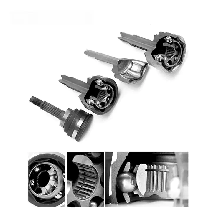
Keeping your CV boots in good condition will protect your axle and CV joint from moisture, dust, and other debris. Damaged or torn boots will allow dirt and moisture to enter the joint, increasing the chances of joint failure.
The most obvious symptom of a worn or torn CV boot is a leaking grease reservoir. When your axle rotates, centrifugal force pushes out the exposed grease. This can travel to other parts of your vehicle and cause problems. If the grease is leaking, then you may need to replace your CV boot.
Another symptom of a damaged CV boot is a loose CV joint. This can cause vibrations and a clicking sound. The joint may even make a popping sound when you turn your wheel.
The most important aspect of a CV boot is its ability to protect your CV joint from moisture and debris. Dirt, dust, and road debris are a few of the worst things to enter a joint. These things can damage it over time and lead to more serious problems.
The good news is that a damaged or torn CV boot isn’t too difficult to repair. Most CV boot repair kits come with a tube of grease, which you will need to repack the joint.
If you are unsure about whether you need to replace your CV boot or CV joint, then you should have a professional inspect it. This will help you determine if the joint needs to be replaced or repaired.
You may also want to take your car for a drive to see if you can notice any changes in the sound. This can be due to a loose CV joint or a broken transmission mount.
The best way to tell if your CV boot needs to be replaced is to look for the first sign of wear. This could be the first time you notice a leaking grease reservoir or a crack in your boot. If this is the case, then you need to take your vehicle to a repair shop.
Knocking sound
Having a CV joint makes it possible for your wheels to turn when your suspension moves. This is essential to your vehicle. A CV joint is often used to absorb a high amount of horizontal axis motion.
While you can find CV joints in most modern cars, they can wear out. It’s important to make sure they are in good condition. If they are not, you could end up with a bad joint that could damage other parts of your vehicle.
A CV joint is a critical part of your vehicle, and you need to keep them in good condition. They may not last forever, so you should consider taking them in for repairs if they start making noise.
Often, CV joints make a clunking or knocking noise. This is because the metal parts of the joint are rubbing against each other. Grease is usually used as a lubricant. It helps reduce friction and increases the lifespan of the joint.
If you hear a CV joint clunk or knocking noise while you are turning, it is likely that the joint is worn out. You should be able to find out if it is by turning the steering wheel to the right and left. This will reveal if the joint is broken or not. If it is, the clunking or knocking noise will be louder as you turn.
Usually, the best way to test your CV joint is to take your car to a mechanic. You can also try to shake the joints to determine if they are worn out. You can also try putting your car in reverse and seeing if the noise gets worse.
If the clunk or knocking sound is not as loud as you expect, you may have a bad CV joint. You could also damage the joint by driving the vehicle with a damaged CV joint. This can be dangerous, so you should take all of your precautions when doing this.
Besides clunking and knocking, you may also hear clicking or a popping noise. These are often indicators that the CV joint is worn out, and may need to be replaced.
Vibrations

Depending on the type of vehicle you drive, you may have vibrations in your CV joint. A CV joint is an important component of your vehicle that allows your wheels to be steered smoothly. The joint is located at the end of each axle.
A worn CV joint will allow the wheels to shake during acceleration. This can be an indicator of a bad axle, which will need to be replaced. It is also a sign of a tire or wheel runout. If the joint is damaged, you may also hear a clicking noise when turning.
If you experience vibrations in your CV joint, you will want to get them fixed as soon as possible. The joint should be inspected before repairs are made.
A damaged CV joint is typically caused by a tear in the joint boot. If the boot is damaged, water or dirt can enter the joint and eventually destroy the steel balls within the joint. You will also be unable to use ordinary chassis grease to lubricate the joint. You will need to use special high-temperature grease.
A bent rim can also cause harmonic vibrations. If you are overtaking another car, you may hear vibrations that are more noticeable at slower speeds. If you are cruising, you will not hear these vibrations. The best way to get them under control is to turn your wheel straight.
In addition to vibrations, your CV joint may also make a clicking or clunking noise. This noise can be caused by a problem with the driveshaft CV joint or by an improper motor/transmission mount.
CV joints can also become damaged by water, dirt and moisture. If water seeps into the joint, you will need to have the joint replaced. You may also need to replace the CV boot. This will help prevent water and dirt from entering the joint.
If you notice vibrations in your CV joint during acceleration, it is important to get them fixed as soon as possible. This can compromise the safety of you and other drivers on the road.
Dangers of a broken CV joint

Having a bad CV joint can be dangerous. Besides the obvious danger of a broken axle, your vehicle may not be safe to drive. Having a bad CV joint can also affect other suspension components, making your car bounce or shake while you drive.
The CV joint is a part of the vehicle’s suspension that allows drivers to control the wheels through the steering wheel. If a CV joint fails, it will be unable to distribute power from the transmission to the wheels. Having a bad CV joint can be hazardous, especially at high speeds. If you suspect that your vehicle has a bad CV joint, it’s best to have it checked immediately.
The first sign of a bad CV joint is an excessive amount of vibration while driving. The more you speed up, the more intense the vibrations will be. A bad CV joint can also cause you to lose control of your vehicle, which can make it difficult to make turns or drive safely.
A loud clicking sound is another common sign of a bad CV joint. The sound is most common during a turn at low speeds, but can also be heard when you accelerate. The click will become louder when the vehicle is turned in a circle.
A clunking sound while decelerating can also be a sign of a bad CV joint. The clunking sound will become louder and more noticeable as the part wears. Having a clunking noise when you turn can be an indication of an inner or outer CV joint failure.
A broken CV joint can leave you stranded and in a dangerous situation. Your car may not move and you may have to tow it. Depending on the location of your vehicle, you may have to replace the entire CV axle, which can be expensive. If you have a broken CV joint, it’s best to have a mechanic inspect it as soon as possible.
A broken CV joint can cause grease to leak into your car, which can cause the tires to wear out faster. It can also cause water and dirt to enter your vehicle.

editor by czh