Product Description
| Spicer | P (mm) | R (mm) | Caterpillar | Precision | Rockwell | GKN | Alloy | Neapcon | Serie | Bearing type |
| 5-2002X | 33.34 | 79 | 644683 | 951 | CP2002 | HS520 | 1-2171 | 2C | 4LWT | |
| 5-2117X | 33.34 | 79 | 316117 | 994 | HS521 | 1-2186 | 2C | 4LWD | ||
| 5-2116X | 33.34 | 79 | 6S6902 | 952 | CP2116 | 1063 | 2C | 2LWT,2LWD | ||
| 5-3000X | 36.5 | 90.4 | 5D9153 | 536 | HS530 | 1711 | 3-3152 | 3C | 4LWT | |
| 5-3014X | 36.5 | 90.4 | 9K1976 | 535 | HS532 | 3C | 2LWT,2LWD | |||
| 5-4143X | 36.5 | 108 | 6K 0571 | 969 | HS545 | 1689 | 3-4143 | 4C | 4HWD | |
| 5-4002X | 36.5 | 108 | 6F7160 | 540 | CP4002 | HS540 | 1703 | 3-4138 | 4C | 4LWT |
| 5-4123X | 36.5 | 108 | 9K3969 | 541 | CP4101 | HS542 | 1704 | 3-4123 | 4C | 2LWT,2LWD |
| 5-4140X | 36.5 | 108 | 5M800 | 929 | CP4130 | HS543 | 3-4140 | 4C | 2LWT,2HWD | |
| 5-1405X | 36.5 | 108 | 549 | 1708 | 4C | 4LWD | ||||
| 5-4141X | 36.5 | 108 | 7M2695 | 996 | 4C | 2LWD,2HWD | ||||
| 5-5177X | 42.88 | 115.06 | 2K3631 | 968 | CP5177 | HS555 | 1728 | 4-5177 | 5C | 4HWD |
| 5-5000X | 42.88 | 115.06 | 7J5251 | 550 | CP5122 | HS550 | 1720 | 4-5122 | 5C | 4LWT |
| 5-5121X | 42.88 | 115.06 | 7J5245 | 552 | CP5101 | HS552 | 1721 | 4-5127 | 5C | 2LWT,2LWD |
| 5-5173X | 42.88 | 115.06 | 933 | HS553 | 1722 | 4-5173 | 5C | 2LWT,2HWD | ||
| 5-5000X | 42.88 | 115.06 | 999 | 5C | 4HWD | |||||
| 5-5139X | 42.88 | 115.06 | 5C | 2LWD,2HWD | ||||||
| 5-6102X | 42.88 | 140.46 | 643633 | 563 | CP62N-13 | HS563 | 1822 | 4-6114 | 6C | 2LWT,2HWD |
| 5-6000X | 42.88 | 140.46 | 641152 | 560 | CP62N-47 | HS560 | 1820 | 4-6143 | 6C | 4LWT |
| 5-6106X | 42.88 | 140.46 | 1S9670 | 905 | CP62N-49 | HS565 | 1826 | 4-6128 | 6C | 4HWD |
| G5-6103X | 42.88 | 140.46 | 564 | 1823 | 4-6103 | 6C | 2LWT,2LWD | |||
| G5-6104X | 42.88 | 140.46 | 566 | 1824 | 4-6104 | 6C | 4LWD | |||
| G5-6149X | 42.88 | 140.46 | 6C | 2LWD,2HWD | ||||||
| 5-7105X | 49.2 | 148.38 | 6H2577 | 927 | CP72N-31 | HS575 | 1840 | 5-7126 | 7C | 4HWD |
| 5-7000X | 49.2 | 148.32 | 8F7719 | 570 | CP72N-32 | HS570 | 1841 | 5-7205 | 7C | 4LWT |
| 5-7202X | 49.2 | 148.38 | 7J5242 | 574 | CP72N-33 | HS573 | 1843 | 5-7207 | 7C | 2LWT,2HWD |
| 5-7203X | 49.2 | 148.38 | 575 | CP72N-55 | 5-7208 | 7C | 4LWD | |||
| 5-7206X | 49.2 | 148.38 | 572 | CP72N-34 | 1842 | 5-7206 | 7C | 2LWT,2LWD | ||
| 5-7204X | 49.2 | 148.38 | 576 | CP72N-57 | 5-7209 | 7C | 2LWD,2HWD | |||
| 5-8105X | 49.2 | 206.32 | 6H2579 | 928 | CP78WB-2 | HS585 | 1850 | 6-8113 | 8C | 4HWD |
| 5-8200X | 49.2 | 206.32 | 581 | CP82N-28 | 1851 | 6-8205 | 8C | 4LWT |
/* January 22, 2571 19:08:37 */!function(){function s(e,r){var a,o={};try{e&&e.split(“,”).forEach(function(e,t){e&&(a=e.match(/(.*?):(.*)$/))&&1
| Condition: | New |
|---|---|
| Certification: | ISO, Ts16949 |
| Structure: | Single |
| Material: | 20cr |
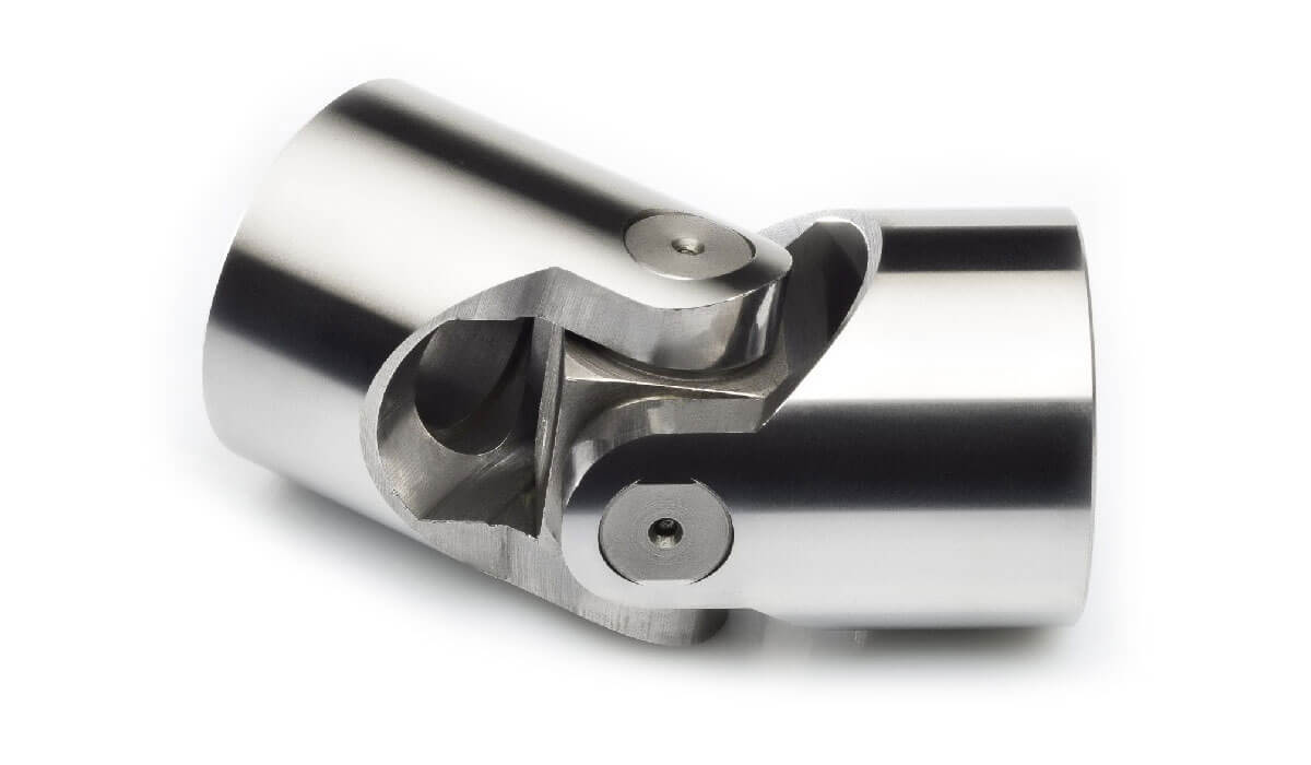
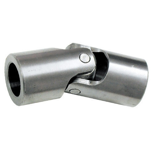
| Type: | Universal Joint |
| Transport Package: | Box + Plywood Case |
| Samples: |
US$ 10/Piece
1 Piece(Min.Order) | |
|---|
| Customization: |
Available
| Customized Request |
|---|

How do you properly maintain and lubricate a universal joint?
Maintaining and lubricating a universal joint is essential to ensure its smooth operation, extend its lifespan, and prevent premature failure. Here’s a detailed explanation of the proper maintenance and lubrication process:
To properly maintain and lubricate a universal joint, follow these steps:
- Consult Manufacturer Guidelines: Refer to the manufacturer’s guidelines and recommendations specific to the universal joint being used. Manufacturers often provide detailed instructions regarding maintenance intervals, lubrication types, and procedures. Familiarize yourself with these guidelines before performing any maintenance or lubrication.
- Inspect the Joint: Regularly inspect the universal joint for signs of wear, damage, or misalignment. Look for indications of excessive play, corrosion, fatigue, or any other abnormalities. Inspecting the joint allows you to identify potential issues before they escalate. If any problems are detected, address them promptly to prevent further damage or failure.
- Clean the Joint: Before applying lubrication, clean the universal joint to remove any dirt, debris, or old lubricant that may have accumulated. Use a suitable cleaning agent or solvent recommended by the manufacturer. It’s important to have a clean surface for effective lubrication.
- Select the Proper Lubricant: Choose the appropriate lubricant specified by the manufacturer. The type of lubricant required may vary based on factors such as the universal joint design, operating conditions, and temperature range. Common lubricants used for universal joints include grease or oil. Ensure that the selected lubricant is compatible with the joint’s materials and operating environment.
- Apply Lubricant: Apply the lubricant to the universal joint according to the manufacturer’s instructions. Pay attention to the specific lubrication points, such as the bearing caps, needle bearings, or trunnions. Use the recommended amount of lubricant to ensure proper coverage and distribution. Avoid over-lubrication as it can lead to excessive heat generation and increased friction.
- Operate the Joint: After lubrication, operate the universal joint to distribute the lubricant evenly and ensure it reaches all necessary components. Rotate or move the joint through its full range of motion several times to facilitate the spreading of the lubricant and to verify smooth operation. This step helps to eliminate any air pockets and ensures that all surfaces are adequately lubricated.
- Monitor and Reapply: Regularly monitor the universal joint’s performance and lubrication condition. Periodically check for any signs of lubricant breakdown, contamination, or leakage. Depending on the manufacturer’s recommendations, reapply lubrication at specified intervals or when necessary to maintain optimal operation. Factors such as operating conditions, load, and temperature may influence the frequency of lubrication.
- Keep Records: Maintain a record of the universal joint’s maintenance activities, including lubrication dates, lubricant type, and any observations made during inspections. These records can help establish a maintenance schedule, track the joint’s performance over time, and serve as a reference for future maintenance or troubleshooting.
By following these steps and adhering to the manufacturer’s guidelines, you can properly maintain and lubricate a universal joint, promoting its longevity, reliability, and optimal performance.

How do you calculate the operating angles of a universal joint?
Calculating the operating angles of a universal joint involves measuring the angular displacement between the input and output shafts. Here’s a detailed explanation:
To calculate the operating angles of a universal joint, you need to measure the angles at which the input and output shafts are misaligned. The operating angles are typically expressed as the angles between the axes of the two shafts.
Here’s a step-by-step process for calculating the operating angles:
- Identify the input shaft and the output shaft of the universal joint.
- Measure and record the angle of the input shaft relative to a reference plane or axis. This can be done using a protractor, angle finder, or other measuring tools. The reference plane is typically a fixed surface or a known axis.
- Measure and record the angle of the output shaft relative to the same reference plane or axis.
- Calculate the operating angles by finding the difference between the input and output shaft angles. Depending on the arrangement of the universal joint, there may be two operating angles: one for the joint at the input side and another for the joint at the output side.
It’s important to note that the specific method of measuring and calculating the operating angles may vary depending on the design and configuration of the universal joint. Some universal joints have built-in methods for measuring the operating angles, such as markings or indicators on the joint itself.
Additionally, it’s crucial to consider the range of acceptable operating angles specified by the manufacturer. Operating a universal joint beyond its recommended angles can lead to increased wear, reduced lifespan, and potential failure.
In summary, calculating the operating angles of a universal joint involves measuring the angular displacement between the input and output shafts. By measuring the angles and finding the difference between them, you can determine the operating angles of the universal joint.

Can you explain the purpose of a universal joint in a drive shaft?
In a drive shaft, a universal joint serves a crucial purpose in transmitting rotational motion between the engine or power source and the driven wheels or other components. Let’s delve into the purpose of a universal joint in a drive shaft:
A drive shaft is a mechanical component that transfers torque from the engine or power source to the wheels or other driven components in a vehicle or machinery. It is typically used in rear-wheel drive and four-wheel drive systems. The drive shaft connects the transmission output shaft to the differential or axle assembly, allowing the wheels to receive power and propel the vehicle forward.
The purpose of a universal joint in a drive shaft is to accommodate the misalignment and changes in angles between the transmission and the differential or axle assembly. Misalignment can occur due to various factors, including the vehicle’s suspension system, the position of the engine, and the movement of the wheels. Without a flexible coupling mechanism, misalignment would cause binding, vibration, and potential damage to the drive shaft and other drivetrain components.
Universal joints provide the necessary flexibility and articulation to compensate for misalignment and changes in angles. They allow the drive shaft to bend and rotate at varying angles while transmitting torque from the transmission to the differential. The universal joint allows the drive shaft to operate smoothly and efficiently, even when the vehicle is in motion and the suspension system causes changes in the relative positions of the transmission and the differential.
When the engine or power source rotates the drive shaft, the universal joint allows angular displacement between the transmission and the differential. As the drive shaft bends and changes angles, the universal joint accommodates these movements, ensuring continuous torque transmission without placing excessive stress on the drivetrain components.
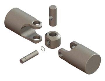
The universal joint consists of a cross-shaped or H-shaped yoke with bearings at the ends of each arm. These bearings allow for smooth rotation and minimize friction between the yoke and the drive shaft. The design of the universal joint enables it to flex and articulate, compensating for misalignment and changes in angles without affecting the rotation of the drive shaft.
Overall, the purpose of a universal joint in a drive shaft is to provide the necessary flexibility and articulation to accommodate misalignment and changes in angles. By allowing the drive shaft to bend and rotate at varying angles, the universal joint ensures smooth and efficient torque transmission between the engine and the driven wheels or components, contributing to the proper functioning of the vehicle or machinery.


editor by CX 2024-03-27